
Installation Guide
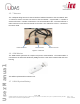
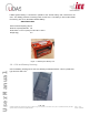
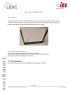
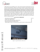
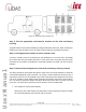
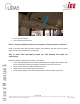
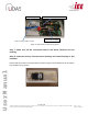
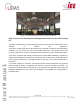
Table Of Contents

Page
15
of
16
Ver No.: 0.11D
Ver Date: 05-05-2020
Information included in this document is the property of IEE S.A. Copy, use or disclosure of its contents, even in part, is not permitted without the prior written
agreement of IEE. This document is strictly IEE confidential.
User Manual
Power connector cable from CCU
Figure 14: Connection to the bus fuse panel
Step 7: Make sure all the connected sensors and driver interface unit are
working
Step 8: Insert the sensors into the sensor housing and install housing to bus
headliner
Ensure that the sensor is correctly locked as shown in figure 15 and mount sensor housing to
bus headliner using screws.
.
Figure 15: Sensor inserted in housing
Wire to vehicle ground
Wire to vehicle battery +13V terminal
Wire to vehicle Ignition