
Installation Guide
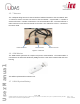
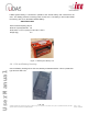
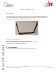
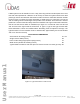
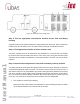
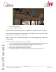
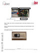
Table Of Contents

Page
14
of
16
Ver No.: 0.11D
Ver Date: 05-05-2020
Information included in this document is the property of IEE S.A. Copy, use or disclosure of its contents, even in part, is not permitted without the prior written
agreement of IEE. This document is strictly IEE confidential.
User Manual
Figure 13: Wire Channel Panel for Route the Sensor Harness
• CCU to Driver interface
• CCU to School bus Fuse box.
Step 5: Connect individual sensors to respective T harness sensor connector
Keep in mind that UCDs with odd node numbers are installed on left side of the bus (driver
side) and even node numbers are on right side.
Step 6: Place CCU and battery inside the CCU housing and make the
connections
Below are listed the required connections in the system:
• +13 V and GND terminals of the LiDAS system battery and Ignition wire from bus fuse
box to CCU power connector and plug in the power connector to the CCU
• Plug in driver interface module harness to the CCU
• Plug in sensor LIN network harness to the CCU
• LiDAS system battery +13V and GND terminals to vehicle battery via fuse box