
Installation Guide
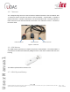
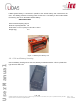
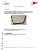

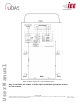
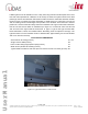
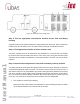
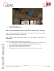
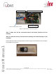
Table Of Contents

Page
13
of
16
Ver No.: 0.11D
Ver Date: 05-05-2020
Information included in this document is the property of IEE S.A. Copy, use or disclosure of its contents, even in part, is not permitted without the prior written
agreement of IEE. This document is strictly IEE confidential.
User Manual
Figure 12: Detection field of single UCD
Step 2: Find an appropriate non-intrusive location for the CCU and battery
housing
A typical location for the CCU and battery housing is behind the driver seat. Other nonintrusive
locations may also be utilized, such as under the first passenger seat behind the driver.
Step 3: Find appropriate location for driver interface unit
The Driver Interface Unit can be mounted on the dashboard or in an area that is accessible
by the driver but does not obstruct the driver’s vision of the road. A long wire harness will be
connected to the module to establish the connection between the CCU unit and the driver
interface.
Step 4: Route all the wiring harness from CCU and battery housing location
The wiring should be routed either through the inside of the bus panel (advised) or should be
covered with appropriate cable concealer. The sensor harness should be secured in such a
way that the harness is not susceptible to any motion. Wiring harness if allowed to move freely
can rub on metallic or sharp edges causing damage to the wiring and result in sensor failure.
Use a tie strap as required to bundle and attach the harness to the bus to prevent any slack
in the wire. The main three connections and its harness route are listed below.
• CCU module to sensors (LIN network)
Remove the wire channel panel and install the T-Harness through the panel to obtain
the connection between CCU module and the sensors.