
Installation Guide
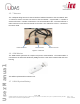
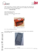
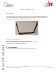

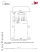
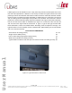
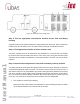
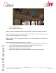
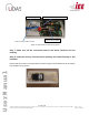
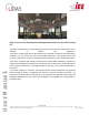
Table Of Contents

Page
12
of
16
Ver No.: 0.11D
Ver Date: 05-05-2020
Information included in this document is the property of IEE S.A. Copy, use or disclosure of its contents, even in part, is not permitted without the prior written
agreement of IEE. This document is strictly IEE confidential.
User Manual
LiDAS system must be installed in such a way that using minimum number(One UCD cover
two seat rows separated at a distance of 35 Inches) of UCDs the system should cover total
passenger volume and detection field must be within the bus to avoid false detection outside
the bus. Figure 11 shows the typical orientation of UCD sensor on school bus. The sensor
and its housing should install length wise parallel to the windows and transceiver antenna
position of a sensor should be exactly above the seat back rest. Figure 12 shows the detection
field of one UCD sensor which is installed as per figure 11. It covers 80° from front to back
and 34° from left to right inside the school bus. In Type A, Type C and Type D buses with
below dimensions, UCDs are installed above alternating seats for optimum coverage. The
typical location is on the headliner closer to window side; approximately 22 cm from window
and 75 cm from the seat top.
Figure 11: Typical orientation of UCD sensor
BUS TYPICAL DIMENSIONS
Seat Cushion to Ceiling (Inches)
57 - 59
Single cushion width (Inches)
39
Floor to side ceiling height (lowest part) (Inches)
75
Width of bus (window to window) (Inches)
90
Typical distance between seat rows (front of cushion to front of cushion) (Inches)
35