
Instructions


IDUINO for maker’s life
www.openplatform.cc
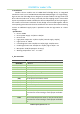
“UR1”
Pull up resistor
“UR2”
Pull up resistor
“UR3”
Pull up resistor
“UR4”
Pull up resistor
“5V_EN”
5V source jumper. When the jumper is put on, The
78M05 supplies the 5V power for the logic circuit on
the board from the VMS port(7V < VMS < 18V). The
power of logic circuit of the board is supplied by the
5V port when this jumper put off.
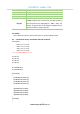
3. Example
This module can drive 2 channel DC motor or 2 phase stepper motor.
For 2 channel DC motor, connection and code as below:
Connection:
IN1==========13;
IN2==========12;
IN3==========11;
IN4==========10;
********Code begin********
int in1=13;
int in2=12;
int in3=11;
int in4=10;
int speedPinA=6;
int speedPinB=5;
void setup()
{
pinMode(in1,OUTPUT);
pinMode(in2,OUTPUT);
pinMode(in3,OUTPUT);
pinMode(in4,OUTPUT);
digitalWrite(in1,HIGH);
digitalWrite(in2,HIGH);
digitalWrite(in3,HIGH);
digitalWrite(in4,HIGH);
}
void loop()
{