
Datasheet


Specifications of the HT2 MOA3 S20 Rev. 1.1 1997-08-19
Ht2moa3.doc/HS Page 10 of 22
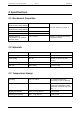
4 Coil Specifications
The HITAG 2 chip module has to be connected to a coil whose parameters are briefly described
in the following.
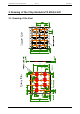
Equivalent circuit of the transponder
Xpc Rpc Cp
Uc
Cchip Rchip
U
c
... voltage at the connection pads
f
res
... resonant frequency of the transponder
X
pc
... parallel reactance of the coil (f = 125 kHz)
R
pc
... parallel resistance of the coil (f = 125 kHz)
C
p
... parasitic capacitance of the package
C
chip
... capacitance of the chip (U
c
> 4 Vpp)
R
chip
... resistance of the chip
f
resc
... self resonant frequency of the coil
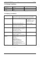
L
pc
=
X
pc
/2πf (f = 125 kHz)
L
pc
=
7.72 mH ± x % (C
p
= 0, x depends on the coil production process)
C
chip
= 210 pF ± 10 %
R
pc
> 45 k
f
resc
> 750 kHz
Note: The parasitic capacitance of the package (C
p
) must be considered.
()
()
f
1
2(C C).L
125 kHz L =
1
2f C + C
res
chip p pc
pc
res chip p
=
+
=⇒
π
π
2
Typical values for C
p
hot laminated cards: C
p
= 1.5 pF
moulded tags: C
p
= 6.0 pF