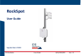
Mod: MDM/011/M4 Rev 1 RockSpot User Guide September 2020 IDS GeoRadar User Guide QGG/2020/002 Rev. 1.
Mod: MDM/011/M4 Rev 2 1 Important Information about your Instrument Read and follow the Quick Guide before using the product or the accessories delivered with the product. ☞ Keep for future reference! Intended use The intended use is the real time detection of fast-moving geological event, such as rockfall, debris flow, snow avalanche, etc. in one of the following possible environments: • open pit mines and quarries • natural landslides • glaciers • snowy slopes • tailing dams.
Mod: MDM/011/M4 Rev 2 Conformity to European regulations This equipment is compliant with the essential requirements and other relevant provisions of Directive 2014/53/UE. The full Declaration of its Conformity can be found either on the CD or a separate document included with this product. This is a Class A product. In a domestic environment it may cause radio interference. If so, the user may need to take adequate measures. Conformity to U.S regulations.
Mod: MDM/011/M4 Rev 2 Information can be obtained at http://www.hc-sc.gc.ca/ewhsemt/pubs/radiation/radio_guide-lignes_direct-eng.php. . Changes or modifications not expressly approved by the party responsible for compliance could void the user's authority to operate the equipment. . . This product complies with FCC and ISED radiation exposure limits set forth for an uncontrolled environment. The antenna should be installed and operated with minimum distance of 30 cm between the radiator and your body.
Mod: MDM/011/M4 Rev 2 de I'exigence de Santé Canada. Les informations peuvent être obtenues: http://www.hcsc.gc.ca/ewh-semt/pubs/radiation/radio_guide-lignes_direct-eng.php . Les changements ou modifications non expressément approuvés par la partie responsable de la conformité pourraient annuler l'autorité de l'utilisateur à utiliser cet équipement. . This device contains license-exempt transmitter(s)/receiver(s) that comply with Innovation, Science and Economic Development Canada's license-exempt RSS(s).
Mod: MDM/011/M4 Rev 2 Canadian Representative: Company Name: Leica Geosystems Ltd Company Number: 3177B Company Address: 1-3761 Victoria Park Ave City: Scarborough Province/State: Ontario Postal Code: M1W 3S2 Country: Canada Contact Name: Sudha Sachdeva Phone Number: +1 416 497 2463 Email: sudha.sachdeva@leicaus.com IDS GeoRadar User Guide QGG/2020/002 Rev. 1.
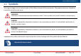
Mod: MDM/011/M4 Rev 2 1.1 Symbols Warning messages are an essential part of the Safety Concept of the instrument. They appear wherever hazards or hazardous situations can occur. WARNING Indicates an imminently hazardous situation which, if not avoided, will result in death or serious injury. DANGER Indicates a potentially hazardous situation or an unintended use which, if not avoided, could result in death or serious injury.
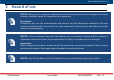
Mod: MDM/011/M4 Rev 2 2 Hazard of use NOTICE: Watch out for erroneous measurement results if the product has been dropped or has been misused, modified, stored for long periods or transported. Precautions: Periodically carry out test measurements and perform the field adjustments indicated in the user manual, particularly after the product has been subjected to abnormal use and before and after important measurements.
Mod: MDM/011/M4 Rev 2 DANGER During the setup and the use of the product, the user must take care of the danger related to the environment surrounding the product, such as obstacles, excavations, traffic etc… Precautions During the operations of the product, the user must be fully aware of the existing dangers. DANGER: During the setup of the product, the user must take care of the danger related to installing and working at height.
Mod: MDM/011/M4 Rev 2 DANGER: If the product is used with accessories, you may increase the risk of being struck by lightning. Precautions: Do not use or maintain the product in a thunderstorm. CAUTION: High mechanical stress, high ambient temperatures or immersion into fluids can cause leakage, fire or explosions of the batteries. Precautions: Protect the batteries from mechanical influences and high ambient temperatures. Do not drop or immerse batteries into fluids.
Mod: MDM/011/M4 Rev 2 Before shipping the product or disposing of it, discharge the batteries by running the product until they are flat. When transporting or shipping batteries, the person in charge of the product must ensure that the applicable national and international rules and regulations are observed. Before transportation or shipping contact your local passenger or freight transport company.
Mod: MDM/011/M4 Rev 2 Install the system using Personal Protective Equipment (PPE) as protective and high visibility clothing, hard helmets, rigger gloves safe goggles, safe steel-toe boots. DANGER: High voltage (110-230 VAC) in the CU Precautions: In order to operate on the internal components of the CU for maintenance purposes switch OFF the system, Unplug the AC cable and insert the LockOut-TagOut (LO-TO) device (metal bar) before opening the CU.
Mod: MDM/011/M4 Rev 2 WARNING: the base of the pole is 45 cm large and needs a concrete block (80 kg of minimum weight) to be fixed using 8 chemical anchors, provided with the pole. Make sure pole is well stable and fixed on its concrete block.
Mod: MDM/011/M4 Rev 2 3 SYSTEM SPECIFICATIONS 3.1 PerformanceSpecifications Intrinsic system specifications are listed in this paragraph. Actual performance may strongly depend on external factors listed in Table 4. 3.1.1 Detection The following specifications refer to a system operating a single Survey Unit.
Mod: MDM/011/M4 Rev 2 Distance from the radar Rock size 500 m 0.6 m 1000 m 2.5 m 2000 m 10 m Tab. 1 – Rockfalls indicative rock size vs distance from the radar. It must be stressed that these figures must be intended as pure indicative values; actual performance can greatly differ, depending on many factors such as the radar-rock line of sight, rock material, number of rocks in the avalanche, angle of fall and velocity, weather conditions etc.
Mod: MDM/011/M4 Rev 2 3.1.2 Tracking Parameter Value Tracking range resolution 4m Tracking azimuth accuracy Up to 1° Track update frequency Up to 2 Hz Table 2 – RockSpot tracking specifications (single Survey unit configuration) Tracking azimuth accuracy of Rockspot are highly dependent on the rock size and number (or size of the avalanche), distance, fall angle, velocity, maximum emitted power, atmospheric conditions etc. 3.1.
Mod: MDM/011/M4 Rev 2 3.1.4 Environmental Specifications Parameter Value Operating Temperature -40 °C ÷ +55 °C Protection IP65 Designed to operate in any weather conditions. Operating conditions Detection, Tracking and Alarm activation performance functions may be affected by strong wind, presence of vegetation, heavy rain or snow falls.
Mod: MDM/011/M4 Rev 2 3.1.5 Radio-Equipment Specifications Parameter Value RF operating band EU:10.50 – 10.60 GHz USA: 10.40 – 10.50 GHz Canada: 10.50 – 10.55 GHz Emission bandwidth EU/USA 100 MHz Canada 50 MHz Maximum power at the antenna connector EU: 17 dBm USA: 31 dBm Canada: 23.7 dBm Antenna Gain 9 dB Equivalent Isotropic Radiated Power (EIRP) EU: 26 dBm USA: 40 dBm Canada: 32.7 dBm Signal modulation Certifications FMCW CE, FCC, ISED Table 5 - RockSpot radio-equipment specifications.
Mod: MDM/011/M4 Rev 2 4 System Breakdown 4.1 System Architecture The RockSpot system architecture is depicted in Fig. A. Fig. A- RockSpot system architecture IDS GeoRadar User Guide QGG/2020/002 Rev. 1.
Mod: MDM/011/M4 Rev 2 The RockSpot system is composed by the following units (Fig. B): - Control Unit, for system control and management - Survey Unit, for data collection and real time data processing Fig. B – RockSpot system overview IDS GeoRadar User Guide QGG/2020/002 Rev. 1.
Mod: MDM/011/M4 Rev 2 4.2 How the system is delivered The system is delivered with two main boxes (Control Unit Box; Survey Unit iCase). Survey Unit Case Control Unit Box IDS GeoRadar User Guide QGG/2020/002 Rev. 1.
Mod: MDM/011/M4 Rev 2 4.2.1 Survey Unit Case The Survey Unit case contains: a) Survey Unit (compact module enclosing the radar sensor, the camera and the GNSS) b) Mounting Brackets and metallic ties c) Control Unit-Survey Unit connection cable of 5m (located under the Survey Unit body). c a IDS GeoRadar b User Guide QGG/2020/002 Rev. 1.
Mod: MDM/011/M4 Rev 2 4.3 Survey Unit installation and setup In case the installation is on a pole, ensure that the pole is properly weighted on the base or coupled with a concrete base 50x50X20cm. 1. Mount the plate on the articulated bracket using T-30 Torx® key. 2. Mount the bracket with the plate on the pole, fixing with the metallic ties, using 7 mm socket wrench, with the tie screw facing the outward side of the pole and placed on the pole as much as close to the bracket. 3.
Mod: MDM/011/M4 Rev 2 4.4 Control Unit installation and setup 1. Install the horizontal bracket on the pole base tightening with metallic ties. 2. Lift the CU by the handles and fix it to the designated brackets supports, tightening with metallic ties using 7 mm socket wrench, tangent and far from the pole as much as possible. 2 1 Apply. isolating or Dutch tape on the sharp- cutting edge of the metallic ties that fix the CU and SU, after HW installation.
Mod: MDM/011/M4 Rev 2 3. Connect the SU to the CU by the designated cable (Error! Reference source not found.) 4. Connect the CU to the SU by inserting the dedicated cable (Error! Reference source not found.) in the connector a ( SU1 red arrow); do not connect the survey unit to the connector c (SU2). In order to supply the CU, connect the designated cable (Error! Reference source not found., Error! Reference source not found.
Mod: MDM/011/M4 Rev 2 5 Switching the system ON/OFF 1 2 1. Switch ON the CU by pressing Power button located on the right edge of bottom side of the CU for 2-3 seconds, until it is possible to observe CONTROL UNIT LED blinking (1s). Turn OFF the CU by pressing the power button (for 6-7 seconds) until the CONTROL UNIT LED turns OFF. 2. The user can access to RockSpot Controller SW running in the embedded PC through the tablet (optional).
Mod: MDM/011/M4 Rev 2 6 Care and Transport In the present section general information about ROCKSPOT system maintenance are provided. All maintenance operations need to be performed with the system stopped and disconnected from the power source. Different behavior can lead to injuries due to mechanical or electrical hazards. Particular attention must be taken in verifying the following (but not limited to): Check that SU bracket’s bearing and tilt nodes are well tightened.
Mod: MDM/011/M4 Rev 2 7 Disclaimer 1 Generals 1.1 The present Disclaimer applies to all products (the “Products”) designed, produced and distributed by IDS GeoRadar s.r.l., its Subsidiaries, Affiliated and authorized Distributors (IDS GeoRadar). IDS GeoRadar. reserves full ownership and intellectual property rights of any “Information” contained in this Disclaimer including Trademarks and Graphics.
Mod: MDM/011/M4 Rev 2 2.3.2 that no operation or use of the ROCKSPOT System shall be started before its designated Operator/s has got the ROCKSPOT User Certificate, as defined by IDS GeoRadar. specific procedure which the Buyer confirms to know and accept. 2.3.3 For Products which include specific “Operational” software with automatic data processing and analysis “Tools”, i.e. the ROCKSPOT system, User shall be aware that the results provided by these “Tools” may be not error free.
Mod: MDM/011/M4 Rev 2 3.3.5 Poor or faulty operation of the electrical and telecommunication networks not directly managed by IDS GeoRadar or its delegates. 3.3.6 Poor or faulty operation Software/Hardware of the third parties connected with IDS GeoRadar . Equipment. 3.3.7 Poor or faulty operation of the Products due to Software Virus which infected the Products after their delivery. 3.3.
Mod: MDM/011/M4 Rev 2 not liable for damages or claims of any kind, which are based on the disregard of such warning messages and / or missing or incorrect actions on behalf of the user. 4.2.3 4.2.3.1 4.2.4 4.2.4.1 4.2.5 4.2.5.1 4.2.6 4.2.6.1 Software failure RockSpot system is designed to operate continuously 24/7, but it may become temporarily unavailable due to software failures.
Mod: MDM/011/M4 Rev 2 can worsen tracking performances and in some circumstances may lead to missing or improper detection. User is responsible to provide and upload a suitable DTM. 4.2.7 GNSS coverage 4.2.7.1 To properly locate and track the rockfall events, RockSpot requires an accurate GNSS measure of the Survey Unit position and orientation.
Mod: MDM/011/M4 Rev 2 4.3.1 4.3.1.1 4.3.2 4.3.2.1 4.3.3 4.3.3.1 4.3.4 4.3.4.1 4.3.5 4.3.5.1 4.3.6 Operating range RockSpot system is designed to operate in a wide range, however system detection performances worsen with increasing distance. Rockfall occurring beyond the RockSpot maximum operating range cannot be detected by the system.
Mod: MDM/011/M4 Rev 2 4.3.6.1 4.3.7 4.3.7.1 4.3.8 4.3.8.1 4.4 4.4.1 4.4.1.1 4.4.2 4.4.2.1 Doppler Radar technology detect the movement only along the Line of Sight (LoS). Rocks falling perpendicularly or close to the perpendicular to the radar LoS could be underestimated or even undetected.
Mod: MDM/011/M4 Rev 2 4.4.3 4.4.3.1 4.4.4 4.4.4.1 4.4.5 4.4.5.1 4.4.6 4.4.6.1 4.4.7 4.4.7.1 4.4.8 Vegetation movements RockSpot system incorporates state-of-the-art algorithms for the correction of vegetation-induced false alarms. However, it must be noted that modelling of real phenomena like vegetation movements leads to an approximation of real-world physics, which may not be always effective, and could introduce false alarms, especially in densely vegetated areas.
Mod: MDM/011/M4 Rev 2 4.4.8.1 4.5 4.5.1.1 RockSpot system is designed to operate together with any other electronic device. However the close presence of instruments that emit electromagnetic waves in the same RF operating band stated in the specifications sheet, may introduce interference signals which, in some circumstances, could limit the radar detection performances.
Mod: MDM/011/M4 Rev 2 8 CUSTOMER SUPPORT For questions please, feel free to contact our Customer Support Service at the following e-mail address: GEO BU Customer Care: support.geo@idsgeoradar.com MIN BU Customer Care: support.mining@idsgeordar.com ©2020 IDS GeoRadar – Part of Hexagon www.ldsgeoradar.com IDS GeoRadar User Guide QGG/2020/002 Rev. 1.
Mod: MDM/011/M4 Rev 2 A. Appendix A In this appendix the datasheet of TX and RX antennas are reported. In particular, the Elevation and Azimuth patterns are shown. It is clearly visible the typical 9 dBi gain at 0° azimuth, 0° elevation direction, both for TX and RX antennas. Figure A – TX Antenna: azimuth beam pattern IDS GeoRadar User Guide QGG/2020/002 Rev. 1.
Mod: MDM/011/M4 Rev 2 Figure B – TX Antenna: elevation beam pattern IDS GeoRadar User Guide QGG/2020/002 Rev. 1.
Mod: MDM/011/M4 Rev 2 Figure C – RX Antenna: azimuth beam pattern IDS GeoRadar User Guide QGG/2020/002 Rev. 1.
Mod: MDM/011/M4 Rev 2 Figure D – RX Antenna: elevation beam pattern IDS GeoRadar User Guide QGG/2020/002 Rev. 1.