
User's Manual

IDS Ingegneria Dei Sistemi S.p.A. N doc: MN/2009/071 - Rev. 1.1
IBIS-S v. 1.0 - User Manual
Config.: IBIS-S-PRCS-OUT-MN
24 / 48
All information contained in this document is property of IDS. All rights reserved.
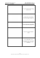
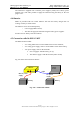
(a)
(b)
Fig. 4.2 – Rear (a) and front (b) view of IBIS-S sensor
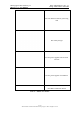
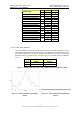
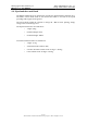
Fig. 4.3 – Bottom view IBIS-S sensor
4.2 Antennas
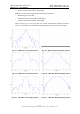
4.2.1 Ku band system antennas
The Ku band IBIS-S system is provided with two identical IBIS-H20 antennas operating
in vertical polarisation and characterised by a maximum gain of 20dBi. The amplitude
characteristics of the antenna main lobe at -3 dB and -10 dB are provided in Tab. 4-1 and
its vertical and horizontal patterns are shown in Fig. 4.4 and Fig. 4.5. For further details
see appendix 6.2C.1 - .
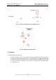
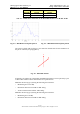
USB
Dovetail guide
housings
Power supply
4 dovetail element
s
for IBIS-L
configuration
Threaded
s
c
rew hole