
User's Manual

IDS Ingegneria Dei Sistemi S.p.A. N°doc: MN/2009/070 - Rev. 1.1
IBIS-L v.02.00 - User manual
54 / 65
All information contained in this document is property of IDS. All rights reserved.
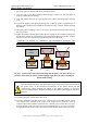
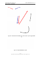
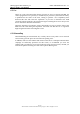
Fig. 4.19 - Left and centre: detail of the IBIS sensor connector. Right: two protective
caps for the connectors
11. connect the power supply cable and the USB cable that are fixed to the trolley of
the linear scanner to the appropriate connectors on the IBIS sensor, being careful
to insert them fully and completely tighten the external ring to ensure the
connections are waterproof;
12. locate the power supply module close to the linear scanner and connect the linear
scanner to the power supply;
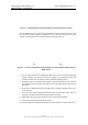
13. connect the power supply module to the linear scanner with the USB cable and
the power supply cable from the IBIS-L C KIT, making sure that the external ring
on each connecter is fully tightened (Fig. 4.20);
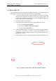
14. position the PC in the upper section of the power supply module, fixing it with the
Velcro harness system;
15. connect the PC power supply cable provided in the power supply module to the
appropriate socket in the PC.
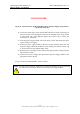
In Fig. 4.21 the fully installed IBIS-L system is shown.
NOTE
: for safety of the operators, remember to connect the equipment to the ground using
the reference screw available in the rear side of the power supply module.