
User's Manual

IDS Ingegneria Dei Sistemi S.p.A. N°doc: MN/2009/070 - Rev. 1.1
IBIS-L v.02.00 - User manual
53 / 65
All information contained in this document is property of IDS. All rights reserved.
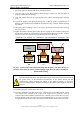
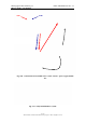
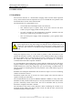
Fig. 4.17 - positioning the elevation pointing system onto the linear scanner
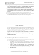
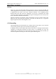
If it the DEM spacers are required, these should be inserted between the trolley and
the elevation pointing system as indicated in Fig. 4.18 (b), following the same
sequence described for the elevation positioning system (points 1-3).
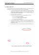
(a)
(b)
Fig. 4.18 – Correctly installed elevation pointing system (a) without and (b) with the
DEM spacers
4. use the same procedure to position the IBIS sensor onto the elevation pointing
system, making sure that the connection flanges are positioned on the side
labelled “antenna side” on the linear scanner and the pointing system;
5. mount the optical view finder onto its guide located on the lid of sensor and lock
it on with its screws (the label on the optical telescope should point in the viewing
direction);
6. mount the two IBIS antennas onto the IBIS sensor, using the supplied screw (4 for
each antenna);
7. unscrew the elevation pointing system fixing nuts and rotate the sensor until it is
pointing in the desired direction using the optical telescope;
8. tighten the fixing nuts again in the hole nearest to the desired position;
9. remove the optical telescope from the sensor;
10. remove the protective caps from the IBIS-L sensor and linear scanner connectors;