
User's Manual

IDS Ingegneria Dei Sistemi S.p.A. N°doc: MN/2009/070 - Rev. 1.1
IBIS-L v.02.00 - User manual
52 / 65
All information contained in this document is property of IDS. All rights reserved.
15. hand tighten the M8 anti veering screw and lock it with an M8 washer and lock nut so that
it keeps the linear scanner flange fixed, without there being any play between the two
screws, but keeping it free to slide for any elongation/contraction due to thermal
excursions undergone while the instrument is positioned at the measurement site;
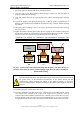
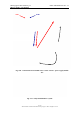
16. place the three remaining spherical thrust bearings, convex side uppermost, onto the three
external studs (the ones that have the track supports inserted), lubricate them with the
water repellent silicon grease and position the concave parts of each one on top of them
(Fig. 4.16);
17. now insert two disc springs and an M16 washer on each of these studs (Fig. 4.16);
18. screw on the M16 fixing nuts to these three studs and hand tighten them, being careful not
to tighten them too much (the disc springs must remain a little open) (Fig. 4.16).
Fig. 4.16 – Steps 16 to 18
The suspension function provided by the spherical thrust bearings maintains the support
horizontal and compensates for any deviation of the position of the studs from the axis
with respect to the horizontal plane of the track, while the springs keep the track fixed to
the supports while permitting it to undergo normal expansion.
When the linear scanner is reinstalled onto an existing installation site, the operations to
be performed are those described in points 4, 5, 8 and then from points 15 to 18 of this
paragraph. The module to be repositioned must simply be placed on the spherical thrust
bearings and then fixed with the M16 nuts and the M8 screw, without touching the
position of the base washers.
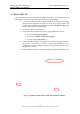
4.2 Installation of the IBIS sensor and module connection
After having installed linear scanner, the IBIS sensor can be installed on the trolley. To do
this, the following operations must be performed in sequence:
1. loosen the two knobs on the trolley dovetail guides sufficiently to permit the
insertion of the elevation pointing system (the sequence of points 1 to 3 is shown
in Fig. 4.17);
2. keeping the pointing system tilted downwards, align the two front pairs of
dovetail guides then rotate the elevation pointing system resting it on the trolley
(loosen further the knobs if it does not completely rest on the trolley);
3. tighten the two knobs;