
User's Manual

IDS Ingegneria Dei Sistemi S.p.A. N°doc: MN/2009/070 - Rev. 1.1
IBIS-L v.02.00 - User manual
45 / 65
All information contained in this document is property of IDS. All rights reserved.
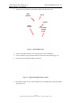
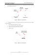
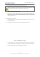
6. block the elevation positioning system at the 5
th
holes counting from the antenna side
in such a way that 5 holes protrude from the back of the pointing system (where the
black knobs are located) (see Fig. 4.3 (a) and Fig. 4.4);
7. orientate the black knobs towards the centre of the box (see Fig. 4.3 (a));
8. tilt the pointing system, lifting the part facing the centre of the box;
9. keeping it tilted, insert the part facing the outside of the box under the protruding part
of the case, being careful to centre it well and completely insert it;
10. rotate the pointing system until it is positioned on the bottom of the case;
11. position the wooden insert on its studs, keeping it slightly tilted towards the outside of
the case;
12. insert the two washes and wing nuts onto the insert studs and tighten them;
13. insert the linear scanner into the case on its three studs (ensure that the linear scanner
trolley is positioned on the middle of the back panel of the linear scanner);
14. insert the three washers and wing nuts and tighten;
15. completely screw in the three template studs;
16. insert the template in the three holes provided;
17. close the box with its lid;
18. secure the box with the six clasps.
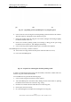
To remove the parts from the IBIS-L case, proceed as follows:
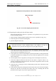
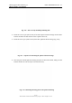
1. sit the case on the ground, open the 7 clasps and lift of the cover;
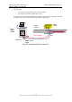
Fig. 4.5 – IBIS-L case
2. after removing the protective layer , you can see:
a. 1 anchoring element;
b. 1 optical telescope;
c. 1 USB cable and one power supply cable for the sensor;
d. 2 locks;