
User's Manual

IDS Ingegneria Dei Sistemi S.p.A. N°doc: MN/2009/070 - Rev. 1.1
IBIS-L v.02.00 - User manual
31 / 65
All information contained in this document is property of IDS. All rights reserved.
The sensor is fitted with two flanges, each with four filleted holes for the installation of
the pair of antennas (see par. 4.2).
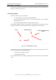
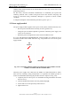
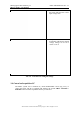
3.3 Linear Scanner
The linear scanner (Fig. 3.15) consists of:
• A 2.5 m long track covered with aluminium sheeting;
• A trolley moved along the track by a step by step motor with a maximum
displacement of 2 m;
• An elevation pointing system to be installed on the trolley.
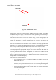
The elevation pointing system is the support for the IBIS sensor and permits the main
beam of the antenna to be orientated in elevation towards the area to be observed.
Fig. 3.15 – Installed linear scanner
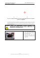
Two mobile connectors link the sliding trolley to the sensor, while the panel at the back of
the linear scanner has the following interfaces:
• A five pin power supply connector;
• A B type USB connector;
to be connected to the power supply unit using the two cables which are part of the IBIS-
C KIT.
Truck
Pointing system
Fixing screw for pointing
system
bogie
base