
User's Manual


IDS Ingegneria Dei Sistemi S.p.A. N°doc: MN/2009/070 - Rev. 1.1
IBIS-L v.02.00 - User manual
26 / 65
All information contained in this document is property of IDS. All rights reserved.
3. IBIS-L SYSTEM HARDWARE CONFIGURATION
This section of the manual provides a detailed description of the components making up
IBIS-L system:
• Par. 3.1 IBIS sensor;
• Par. 3.2 IBIS antennas;
• Par. 3.3 IBIS linear scanner;
• Par. 3.4 Installation kit;
• Par. 3.5 IBIS-PS power supply module;
• Par. 3.6 Control and acquisition PC;
• Par. 3.7 Set of IBIS-C KIT connection cables.
3.1 IBIS sensor
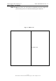
The radar sensor is the unit containing all the parts for the generation, transmission,
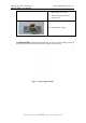
reception and acquisition of the radar signal. The sensor is shown in Fig. 3.1 and can be
seen as a yellow box with dimensions 375x270x115 mm.
Fig. 3.1 – IBIS sensor
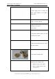
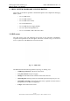
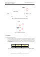
The IBIS sensor has the following interfaces (see Fig. 3.2 and Fig. 3.3):
• 1 USB B type connector at the back of the sensor;
• A 12 pole connector for power supply;
• 2 flanges for installation of the antennas on the front of the box.
• 1 dovetail guide on the top of the box to hold the optical telescope (see par. 4.2).
• 1 threaded screw hole on the bottom of the sensor, required to fix the sensor to
the tripod (for use in IBIS-S configuration.
• 4 clasps on the bottom of the sensor.