
User's Manual
IDS Ingegneria Dei Sistemi S.p.A. N doc: MN/2009/071 - Rev. 1.1
IBIS-S v. 1.0 - User Manual
47 / 48
A
ll information contained in this document is property of IDS. All rights reserved.
APPENDIX C - ELEMENTS OF RADAR TECHNOLOGY
C.1 - Definitions
C.1.1 M
ain antenna lobe
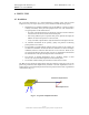
The term antenna main lobe (or beam) is intended as the angular area within which the
antenna concentrates most of the power it is supplied with.
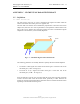
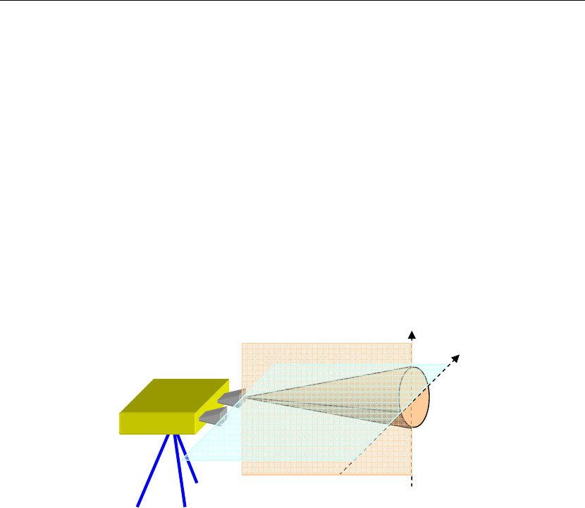
The main lobe of an antenna can be schematically represented as a truncated cone with an
elliptic base, where the cone vertex is positioned in correspondence with the antenna. The
base of the cone is elliptical since antennas typically have lobes with different angular
amplitudes in the elevation (V) and azimuth (H) planes.
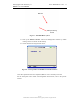
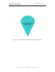
F
ig. C. 1 – Schematic diagram of the antenna beam
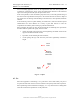
The following parameters are normally defined to quantify the antenna beam amplitude:
• The beam at -3dB: angular area within which antenna gain is more than 50% of the
maximum gain (-3 dB = 10*log
10
(0,5)).
• The beam at -10 by: angular area within which gain is more than 10% of the
maximum gain (-10 dB = 10* log
10
(0,1)).
From an applicative point of view, this means that the sensor must be pointed so that the
scenario of interest falls inside the antenna beam, preferably at -3dB. Therefore the
distance at which the instrument should be positioned and its inclination should be chosen
depending on the antenna beam being used.
V plane
H plane