
User's Manual
IDS Ingegneria Dei Sistemi S.p.A. N doc: MN/2009/071 - Rev. 1.1
IBIS-S v. 1.0 - User Manual
37 / 48
A
ll information contained in this document is property of IDS. All rights reserved.
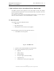
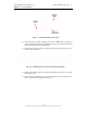
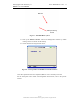
Fig. 5.11 – Sensor installation onto the tripod
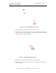
21. Retrieve the optical telescope and loosen the lower screws.
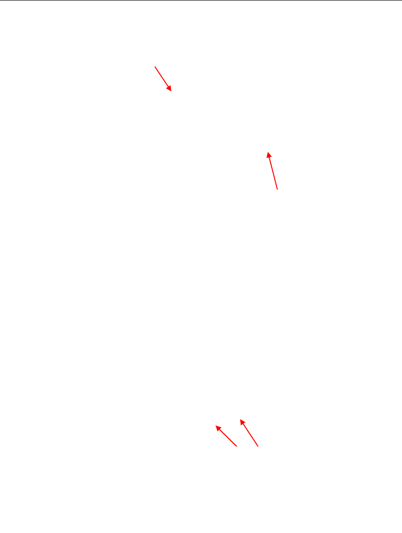
22. Install the optical telescope on the sensor, sliding it into the guide on the top of
the sensor and fix it by tightening the screws (the writing on the telescope
should face the side with the connectors).
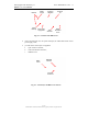
Fig. 5.12 – Mounting the optical telescope
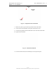
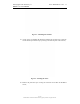
23. Retrieve the two antennas and their fixing screws from the case.
24. Mount the two antennas on the sensor (Fig. 5.13) using the screws provided (4
for each antenna).
Antenna
side
Elevation
handle
Screws for
fixing the
telescope