
User's Manual
IDS Ingegneria Dei Sistemi S.p.A. N doc: MN/2009/071 - Rev. 1.1
IBIS-S v. 1.0 - User Manual
25 / 48
A
ll information contained in this document is property of IDS. All rights reserved.
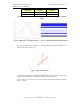
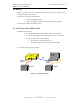
IBIS-ANT3
HORIZONTAL
PLANE
VERTICAL
PLANE
-3 dB
17° 15°
-10 dB
34° 45°
Tab. 4.1 – Width of the main lobes of the IBIS-ANT3-H17V15 antennas at -3 dB and
-10 dB
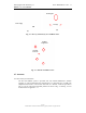
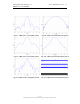
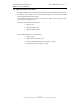
Fig. 4.4 – IBIS-ANT3 vertical plane pattern Fig. 4.5 – IBIS-ANT3 horizontal plane pattern
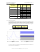
The sensor is fitted with two flanges, each with four filleted holes for the installation of
the pair of antennas (see par. 5.2).
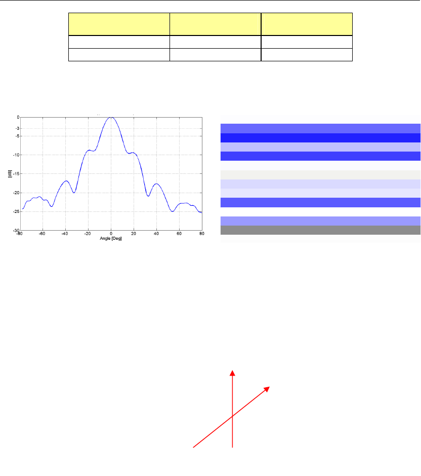
Fig. 4.6 – IBIS-ANT3 antenna
If desired as an optional or a substitution, the IBIS-ANT3 antennas can be replaced by a
pair of three other antennas whose characteristics are reported in Tab. 4.2
Figure from Fig. 4.7 to Fig. 4.12 show the vertical and horizontal patterns of antenna
Type 1, 2 and 4.
V
H