
User's Manual
IDS Ingegneria Dei Sistemi S.p.A. N doc: MN/2009/071 - Rev. 1.1
IBIS-S v. 1.0 - User Manual
24 / 48
A
ll information contained in this document is property of IDS. All rights reserved.
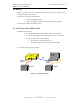
(a)
(b)
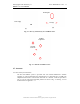
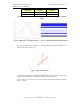
Fig. 4.2 – Rear (a) and front (b) view of IBIS-S sensor
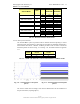
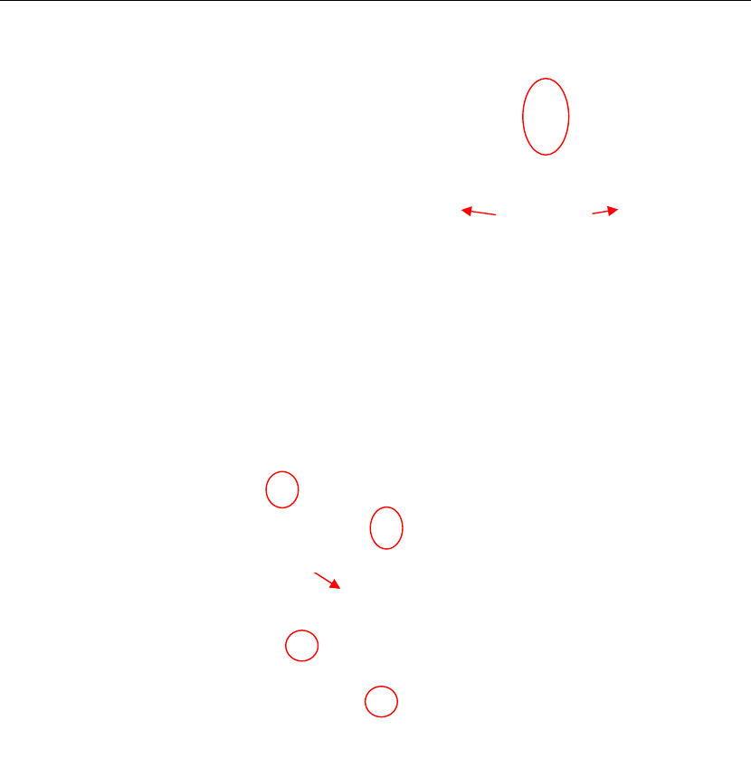
Fig. 4.3 – Bottom view IBIS-S sensor
4.2 A
ntennas
4.2.1 Ku band system antennas
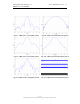
The Ku band IBIS-S system is provided with two identical IBIS-ANT3 antennas
operating in vertical polarisation and characterised by a maximum gain of 19dBi. The
amplitude characteristics of the antenna main lobe at -3 dB and -10 dB are provided in
Tab. 4.1 and its vertical and horizontal patterns are shown in Fig. 4.4 and Fig. 4.5. For
further details see appendix C.1.1.
USB
Dovetail guide
housings
Power supply
4 dovetail elements
for IBIS-L
configuration
Threaded
s
c
rew hole