
User's Manual

IDS Ingegneria Dei Sistemi S.p.A. N doc: MN/2009/071 - Rev. 1.1
IBIS-S v. 1.0 - User Manual
23 / 48
A
ll information contained in this document is property of IDS. All rights reserved.
4. IBIS-S SYSTEM HARDWARE CONFIGURATION
IBIS-S components description is provided in this secti
on of the manual:
• Cap. 4.1 IBIS-S sensor;
• Cap. 4.2 IBIS antennas;
• Cap. 4.3 control and acquisition PC;
• Cap. 0 power supply batteries IBIS-BAT;
• Cap. 4.5 power supply cables kit IBIS-C KIT;
• Cap. 4.6 tripod (IBIS-TR) and three axial head(IBIS-H3).
4.1 I
BIS-S Sensor
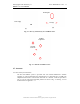
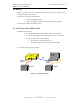
The IBIS-S sensor is the unit containing all the parts for the generation, transmission,
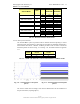
reception and acquisition of the radar signal. The sensor (see Fig. 4.1) is a yellow box
having 375x270x115 mm dimensions.
Fig. 4.1 – IBIS-S sensor
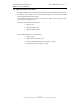
It features the following interfaces (see Fig. 4.2 and Fig. 4.3):
• 1 type A USB Female connector on the rear of the box;
• 1 12 pole Male connector to provide power on the rear of the box;
• 2 housings for the antennas on the front of the box.
• 1 dovetail guide to be used to fix the optical telescope to the sensor (see par. 5.2)
on the top of the box;
• 1 threaded screw hole to permit the sensor to be fitted onto the tripod (see par.
5.2) on the bottom of the box;
• 4 dovetail elements to permit the sensor to be fitted onto the pointing system
positioning module (for IBIS-L configuration).