
User's Manual

IDS Ingegneria Dei Sistemi S.p.A. Protocol: MN/2009/056 - Rev. 1.0
RIS Hi-Mod - Installation Guide and User Manual
27
/
41
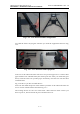
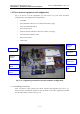
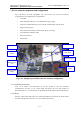
Fig. 1-24 – Main frame “mushrooms” & locking device
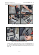
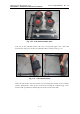
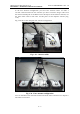
Take the antennas and make them slide in the side frames from behind. Remember
to put and remove the antennas always from the rear part of the frames. When the
antennas are in place lock them around the junction pipes using their hooks (Fig.
1-25).
Fig. 1-25 - Insertion of one antenna and close-up of the hook
1.3.2 Wiring
Battery, wheel and LAN cables are linked to the DAD control unit as in the mono
antenna configuration (see Par 1.1.2 Wiring for further instruction).
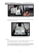
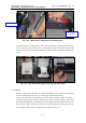
In the three antennas configuration you have three antenna cables. To make a
cascade connection between the antennas you have to link the longer cable from
the ANT1/CHAIN port of the DAD unit to the IN port of the leftmost antenna; use
the two short cable to link OUT and IN ports of each adjacent antenna (Fig. 1-26).
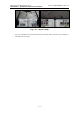
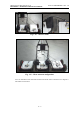
The complete three antenna configuration in shown in Fig. 1-27.
“Mushroom”
Locking
device