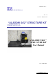
- P RO/010/M1 Rev 3 - INGEGNERIA DEI SISTEMI S.p.A. Rev. 1.2 Protocol: MN/2005/038 “ALADDIN SK2” STRUCTURE KIT USER MANUAL “ALADDIN SK2 ” STRUCTURE KIT User Manual Pisa, 28/06/2006 Tot pag. N°.
IDS Ingegneria Dei Sistemi S.p.A. “ALADDIN SK2 ” STRUCTURE KIT User Manual Protocol: MN/2005/038 - Rev. 1.2 Document Evolution Revision Date Reason of change Rev. 1.0 19/12/2005 First Edition Rev. 1.1 28/06/2006 Upgrade of the survey kit Rev. 1.2 25/07/2006 FCC information included Versions covered by this document K2 01.01.000, 01.02.000, 01.02.002. GRED 3D 01.00.000, 01.00.001, 01.00.002, 01.03.
IDS Ingegneria Dei Sistemi S.p.A. “ALADDIN SK2 ” STRUCTURE KIT User Manual Protocol: MN/2005/038 - Rev. 1.2 IMPORTANT NOTE FOR THE US CUS TOMERS In the US this unit operates under FCC rules Part 15. According to these rules, the system includes a manually operated switch (“dead-man switch”) that causes the transmitter to cease operation within 10 seconds of being released by the operator.
IDS Ingegneria Dei Sistemi S.p.A. “ALADDIN SK2 ” STRUCTURE KIT User Manual Protocol: MN/2005/038 - Rev. 1.2 INDEX 1. INTRODUCTION .......................................................................................................6 1.1 Purpose.................................................................................................................6 1.2 Field of application...............................................................................................6 1.3 Reference ..............
IDS Ingegneria Dei Sistemi S.p.A. “ALADDIN SK2 ” STRUCTURE KIT User Manual Protocol: MN/2005/038 - Rev. 1.2 FIG. 3-4 – REMOVING T HE BIPOLAR ANTENNA............................................................10 FIG. 3-5 – BOTT OM SECT ION...........................................................................................11 FIG. 3-6 – UPPER SECTION..............................................................................................11 FIG. 3-7 – INSERT ING T HE SUPPORT LEGS..................
IDS Ingegneria Dei Sistemi S.p.A. “ALADDIN SK2 ” STRUCTURE KIT User Manual Protocol: MN/2005/038 - Rev. 1.2 1. INTRODUCTION This manual contains a complete description of the "Aladdin" structures kit, including details on how to assemble the kit hardware, use it and operate the software interface 1.1 Purpose This document is intended to be used as a guide for the installation and use of the "Aladdin" structures kit. 1.
IDS Ingegneria Dei Sistemi S.p.A. “ALADDIN SK2 ” STRUCTURE KIT User Manual Protocol: MN/2005/038 - Rev. 1.2 Survey: the name given to a collection of acquisitions, which together cover all the areas of a large investigation: typically an entire town or a large urban area. Scan: a s ingle movement of the antenna trolley from the beginning to the end of a pre-established path. Data processing: this is applied to the raw data to permit the acquired sections to be viewed in a comprehensible way.
IDS Ingegneria Dei Sistemi S.p.A. “ALADDIN SK2 ” STRUCTURE KIT User Manual Protocol: MN/2005/038 - Rev. 1.2 2. SYSTEM COMPONENTS The "Aladdin SK2" structures kit consists of the following parts: 1. bipolar antenna 2. connection box 3. trolley handle. 4. antenna trolley 5. notebook PC. 6. 2CH MCH DAD. 7. 2 cables to connect the D-D 65cm antenna to the DAD. 8. 1 battery. 9. 1 battery charger. 10. USB stick + K2 acquisition software. 11. CD-ROM + GRED 3D processing software. 12. transportation case. 13.
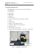
IDS Ingegneria Dei Sistemi S.p.A. “ALADDIN SK2 ” STRUCTURE KIT User Manual Protocol: MN/2005/038 - Rev. 1.2 3. HOW TO SET UP THE SYSTEM 3.1 Opening the case When you receive the case containing the "Aladdin" structures kit, follow the procedure below: Open the protective case, remove the bottom divider and take out the antenna trolley steering handle (see Fig. 3-1). Fig. 3-1 – Opening the case If you want to remove the battery, unscrew the black screw shown in the picture (Fig. 3-2). Fig.
IDS Ingegneria Dei Sistemi S.p.A. “ALADDIN SK2 ” STRUCTURE KIT User Manual Protocol: MN/2005/038 - Rev. 1.2 Undo the Velcro that keeps the DAD unit blocked, now remove the DAD and the trolley (Fig. 3-3). Fig. 3-3 – Removi ng the DAD and the antenna trolley Remove the bipolar antenna, pushing the lever towards the foam support then lift the antenna out rotating it s lightly (see the direction of the red arrow in Fig.
IDS Ingegneria Dei Sistemi S.p.A. “ALADDIN SK2 ” STRUCTURE KIT User Manual Protocol: MN/2005/038 - Rev. 1.2 Fig. 3-5 – Bottom section Undo the Velcro on separator of the top part of the case and lift up the top section (Fig. 3-6). Fig. 3-6 – Upper section Remove the two support legs and insert them in the holes in the bottom of the case (Fig. 3-7).
IDS Ingegneria Dei Sistemi S.p.A. “ALADDIN SK2 ” STRUCTURE KIT User Manual Protocol: MN/2005/038 - Rev. 1.2 Fig. 3-7 – Inserting the support legs Close the lid of the case, inserting the legs into the upper supports (Fig. 3-8). Fig. 3-8 – Fixing the worktable Connect the power cable to the battery then replace the lower cover onto the case to provide a second surface for sitting the material from the kit (Fig. 3-9).
IDS Ingegneria Dei Sistemi S.p.A. “ALADDIN SK2 ” STRUCTURE KIT User Manual Protocol: MN/2005/038 - Rev. 1.2 Fig. 3-9 – Final set-up of the worktable 3.2 Connecting up the system 3.2.1 How to assemble the frame to the antenna As we can notice from the Fig. 3-10 the procedure of assembly of the frame on the antenna is the following: • Link the frame as indicated in the pictures below and then push it up in order to connect it in the lateral white nuts. Fig.
IDS Ingegneria Dei Sistemi S.p.A. “ALADDIN SK2 ” STRUCTURE KIT User Manual Protocol: MN/2005/038 - Rev. 1.2 3.2.2 How to assemble the metric wheel to the frame • Screw the central nut of the metric wheel in the lateral hole located on the frame, keeping the wheel in vertical position (see Fig. 3-11). Fig. 3-11 – Assembly of the metric wheel on the frame 3.2.
IDS Ingegneria Dei Sistemi S.p.A. “ALADDIN SK2 ” STRUCTURE KIT User Manual Protocol: MN/2005/038 - Rev. 1.2 3.2.4 How to assemble the fork and the handle on the frame • In order to assemble the handle it’s necessary to insert the fork at the end of the handle in the point indicated in Fig. 3-13 and then screw the nut. • Then connect the fork of the handle to the frame making pressure on the two white lateral nuts up to link them. Fig. 3-13 – Assembly of the handle to the frame 3.
IDS Ingegneria Dei Sistemi S.p.A. “ALADDIN SK2 ” STRUCTURE KIT User Manual Protocol: MN/2005/038 - Rev. 1.2 Fig. 3-14 – Fixed connection cable between the bi polar antenna trigger box Remote control cable connecting the antenna to the handle (Fig. 3-15); after inserting and tightening the handle screw to the fork connected to the antenna, connect the handle cable to the port situated on the back of antenna labelled "REMOTE" (Fig. 3-15). Fig.
IDS Ingegneria Dei Sistemi S.p.A. “ALADDIN SK2 ” STRUCTURE KIT User Manual Protocol: MN/2005/038 - Rev. 1.2 Fig. 3-16 – Connecting the serial cable 2 65cm D-D cables connecting the trigger box to the DAD (Fig. 3-17); connect the cables respectively to the ports ANT.1 CH1 and ANT.2 CH2 indicated on the DAD and on the trigger box Fig. 3-17 – Connecting the D-D cables LAN cable connecting the PC to the DAD (Fig.
IDS Ingegneria Dei Sistemi S.p.A. “ALADDIN SK2 ” STRUCTURE KIT User Manual Protocol: MN/2005/038 - Rev. 1.2 Fig. 3-18 – LAN cable Cable connecting the battery power supply to the DAD (Fig. 3-19); connect the metallic connector to the DAD and the white plastic connector to the battery. Fig. 3-19 – Power cable Metric wheel cable: connect the cable of the metric wheel to the WHEEL port located on the front side of the antenna (Fig. 3-20). Fig.
IDS Ingegneria Dei Sistemi S.p.A. “ALADDIN SK2 ” STRUCTURE KIT User Manual Protocol: MN/2005/038 - Rev. 1.2 (Optional) Optical reader cable (Fig. 3-21); after having inserted the bipolar antenna in the trolley as shown in Fig. 3-21, connect the optical reader cable to the port labelled "OPTICAL READER". Fig. 3-21 – Optical detector, cable and antenna connection (Optional) Antenna survey wheel cable (Fig.
IDS Ingegneria Dei Sistemi S.p.A. “ALADDIN SK2 ” STRUCTURE KIT User Manual Protocol: MN/2005/038 - Rev. 1.2 3.4 Technical advice Pay special attention to the following technical advice to avoid operational problems: Fix the pad to the surface being investigated with adhesive tape. Avoid treading on the paper pad, this may damage it making it unusable.
IDS Ingegneria Dei Sistemi S.p.A. “ALADDIN SK2 ” STRUCTURE KIT User Manual Protocol: MN/2005/038 - Rev. 1.2 4. HOW TO USE THE SYSTEM 4.1 Main functions To access the "Aladdin" structures kit from the K2 SW (see MN_2004_005), you have to open a dedicated session. Fig. 4-1 – Opening window K2 SW Step 1 Click once with the left mouse button on the "K2" icon contained in the blue bar at the top of the initial K2 SW window (see Fig. 4-1).
IDS Ingegneria Dei Sistemi S.p.A. “ALADDIN SK2 ” STRUCTURE KIT User Manual Protocol: MN/2005/038 - Rev. 1.2 Fig. 4-2 – External device settings command Step 2 this opens the window shown in Fig. 4-3, select RS-232 Aladdin in the External device type field. CLICK ONCE VIRTUAL KEYBO ARD Fig.
IDS Ingegneria Dei Sistemi S.p.A. “ALADDIN SK2 ” STRUCTURE KIT User Manual Protocol: MN/2005/038 - Rev. 1.2 Step 4 Click on the COM Settings button. This will open the window shown in Fig. 4-4, from where you just have to select the Com port number you have used to connect the kit to the structure, then press the OK button Fig. 4-4 – Com settings Window Step 5 Use the Aladdin field shown in the window in Fig. 4-3 to set the acquisition parameters to be used with the structures kit (see Fig. 4-5): Fig.
IDS Ingegneria Dei Sistemi S.p.A. “ALADDIN SK2 ” STRUCTURE KIT User Manual Protocol: MN/2005/038 - Rev. 1.2 The Aladdin field consists of the following parameters: · Automatic: an automatic acquisition mode in which once the other parameters have been set, it is sufficient to press start, stop and any automatic user markers, positioning the system just before the horizontal line shown on the pad. This mode contains automatic data quality control (see the Tolerance field later on).
IDS Ingegneria Dei Sistemi S.p.A. “ALADDIN SK2 ” STRUCTURE KIT User Manual Protocol: MN/2005/038 - Rev. 1.2 is exceeded, the software forces you to repeat the pass being performed. You also have the option of calling up the virtual keyboard by pressing the button shown in Fig. 4-3. To confirm all the set parameters, press the OK button in the window shown in Fig. 4-3.
IDS Ingegneria Dei Sistemi S.p.A. “ALADDIN SK2 ” STRUCTURE KIT User Manual Protocol: MN/2005/038 - Rev. 1.2 Fig. 4-7 – Aladdin System NO TE! The pad consists of a grid of longitudinal and transversal lines that indicate the profiles to be traced using the antenna. In addition, there is a black square at the bottom right hand corner which represents the antenna parking area, containing an optical detector that temporarily deactivates the acoustic signal.
IDS Ingegneria Dei Sistemi S.p.A. “ALADDIN SK2 ” STRUCTURE KIT User Manual Protocol: MN/2005/038 - Rev. 1.2 Fig. 4-8 – Pad for the structures kit Step 3: Position the antenna on the initial preset coordinate (Fig. 4-9) in the L (or T) direction and carefully position the antenna until the acoustic signal stops Fig. 4-9 – Starting position Step 4A (Standard System): Press one of the START buttons placed on the handle or directly on the antenna (Fig.
IDS Ingegneria Dei Sistemi S.p.A. “ALADDIN SK2 ” STRUCTURE KIT User Manual Protocol: MN/2005/038 - Rev. 1.2 Fig. 4-10 – START buttons Step 5: Move the antenna in the pre-established direction; acquisition will start as soon as the optical detector crosses the first horizontal line. Step 6: If you have pre-set "Auto Marker", each time the antenna crosses a horizontal line, the system will insert a User Marker on the scan.
IDS Ingegneria Dei Sistemi S.p.A. “ALADDIN SK2 ” STRUCTURE KIT User Manual Protocol: MN/2005/038 - Rev. 1.2 Fig. 4-11 – Sequence of 2 scans using a 2x2 pad 4.2.2 “Manual” Mode Steps 1-4: Follow the same procedure described for "Automatic" mode above. Step 5: Acquis ition starts when you press the START button, independently of the position of the first horizontal line encountered. Step 6A (Standard System): Insertion of User Markers during scanning is performed by rapidly pressing the START button.
IDS Ingegneria Dei Sistemi S.p.A. “ALADDIN SK2 ” STRUCTURE KIT User Manual Protocol: MN/2005/038 - Rev. 1.2 4.2.3 “Manual (no check)” Mode Step 1-7: In this case the user must use the PSG carpet –Pad Survey Guide Guide (Fig. 4-12) with the slide applied under the frame (see Par. 3.2.3). Fig. 4-12 – PSG Carpet The PSG carpet holds alternated upper and lower guides in order to make the slide perfectly fit and for the antenna to realize straight scans.
IDS Ingegneria Dei Sistemi S.p.A. “ALADDIN SK2 ” STRUCTURE KIT User Manual Protocol: MN/2005/038 - Rev. 1.2 Fig. 4-13 – Features of PSG and slide Follow the same operative procedure used in the "Manual" procedure described above. NOTE! The main difference with respect to the "Manual" mode consists in the absence of the Tolerance control factor, therefore you are free to choose how long the scan should be (Length). This mode is useful when scans of different lengths have to be performed.
IDS Ingegneria Dei Sistemi S.p.A. “ALADDIN SK2 ” STRUCTURE KIT User Manual Protocol: MN/2005/038 - Rev. 1.2 Fig.