
Instruction Manual

83
•
Setting Frequency by Current Reference Input
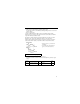
Initial setting of multi-function output terminal
NOTE
Never input voltage reference to control circuit terminal FR when DIP switch
SW2 is switched to “I” side. This could damage the inverter.
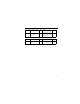
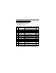
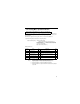
No. Terminals Initial Setting
n057 MA, MB 0 (fault)
n058 P1 1 (in operation)
n059 P2 2 (Frequency agreed)
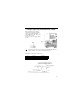
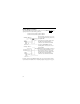
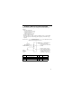
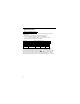
When setting frequency by inputting
current reference (4-20mA or 0-20mA)
from the control circuit terminal FR,
switch the DIP switch SW1 on the control
circuit board to “I” side.
SW1 is accessed by removing the digital
operator.