
Instruction Manual

39
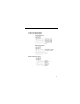
6. PROGRAMMING FEATURES
Factory settings of the parameters are shown as in the tables.
•
Parameter Set-up and Initialization
The following table describes the data which can be set or read when n001 is set.
Unused parameters among n001 to n179 are not displayed.
* Excluding setting disabled parameters.
=
Refer to page 70.
(1) The set values of input terminal function selection 1 to 7 (n050 to n056) are the
same.
(2) The following conditions are not satisfied in the V/f pattern setting:
Max. output frequency (n011) >
Max. voltage output frequency (n013)
> Mid. output frequency (n014)
>
Min. output frequency (n016)
For details, refer to “Adjusting torque according to application” (V/f pattern set-
ting) on page 38.
(3) If the following conditions are not satisfied in the Jump frequency setting:
Jump frequency 3 (n085)<
Jump frequency 2 (n084)
<
Jump frequency 1 (n083)
(4) If Frequency reference lower limit (n034) >
Frequency reference upper limit
(n033)
(5) If motor rated current (n036) >
150% of inverter rated current
(6) When n018 = 0 and n019 ~ n022 is set to a value greater than 600.0 sec, parameter
n018 will automatically be set to 1.
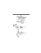
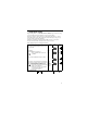
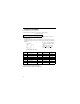
Parameter selection/initialization (n001)
n001 Setting Parameter that can be set Parameter that can be referred
0 n001 n001 to n179
1 n001 to n049* n001 to n049
2 n001 to n079* n001 to n079
3 n001 to n119* n001 to n119
4 n001 to n179* n001 to n179
5 Not used
6 Fault history cleared
8,9,12,13 Not used
10 Initialize
11 Initialize (3-wire sequence)
=
NOTE
“ ” appears on the LED display for one second and the set data returns to
its initial values in the following cases: