
Instruction Manual

34
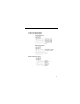
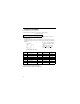
• Monitoring
Following items can be monitored by U-parameter
parameter
No.
Name Description
U-01
Frequency reference
(FREF)*
¹
Hz
Frequency reference can be monitored.
(Same as FREF)
U-02
Output frequency
(FOUT)*
¹
Hz
Output frequency can be monitored.
(Same as FOUT)
U-03
Output current
(IOUT)*
¹
Hz
Output current can be monitored.
(Same as IOUT)
U-04 Output voltage V Output voltage can be monitored.
U-05 DC voltage V Main circuit DC voltage can be monitored.
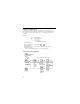
U-06 Input terminal status*
2
—
Input terminal status of control circuit terminals can be
monitored.
U-07 Output terminal status*
2
—
Output terminal status of control circuit terminals can
be monitored.
U-08 Torque monitor %
The amount of output torque can be monitored. When
V/f control mode is selected, “----” is displayed.
U-09 Fault history (last 4 faults) — Last four fault history is displayed.
U-10 Software No. — Software No. can be checked.
U-11 Output power*
3
kW Output power can be monitored
U-13 Cumulative operation time*
4
x10H
Cumulative operation time can be monitored in units of
10H
U-15 Data reception error*
4
—
Contents of MEMOBUS communication data reception
error can be checked. (contents of transmission
register No. 003DH are the same)
U-16 PID feedback*
5
% Input 100(%) / Max. output frequency or equivalent
U-17 PID input*
5
% + 100(%) /+ Max. output frequency
U-18 PID output*
5
% + 100(%) /+ Max. output frequency
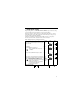
*1 The status indicator LED is not turned ON.
*2 Refer to the next page for input / output terminal status.
*3 The display range is from -99.9kW to 99.99kW.
When regenerating. the output power will be displayed in units of 0.01kW when
-9.99kW or less and in units of 0.1kW when more than -9.99kW.
When in the vector control mode, “----” will be displayed.
*4 This function only applies to 200/400V class 7.5/10hp (5.5/7.5kW) inverters.
*5 Displayed in units of 0.1% when less than 100% and in units of 1% when 100% or
more. The display range is from -999% to 999%.