
Instruction Manual

165
Notes: 1. Not initialized by parameter initalization.
2. Upper limit and initial setting of setting range are doubled at 400 class.
3. Changes depending on inverter capacity. Refer to the next page.
4. Changes depending on inverter capacity. Refer to page 64.
5. Initial setting of the model with operator JVOP-140 (with potentiometer)
is 0. Setting can be set to 1 by parameter initialization.
6. When control mode selection (n002) is changed, initial setting
correspondents to the control mode.
7. Changes depend on inverter capacity. Refer to page 101.
8. Setting value only applies to 200/400V class 7.5/10hp (5.5/7.5kW)
inverters.
9. Parameter value only applies to 200/400V class 7.5/10hp (5.5/7.5kW)
inverters
10. “1” for 200/400V class 7.5/10hp (5.5/7.5kW) inverters
* Values are double with 400V class.
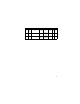
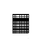
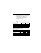
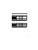
Initial settings that change with inverter capacity
• 200V class 3-phase
No. Name
V / f control mode
(n002 = 0)
Vector control mode
(n002 = 1)
n014 Mid. output frequency 1.3Hz 3.0Hz
n015 Mid. output frequency voltage 12.0V* 11.0V*
n016 Minimum output frequency 1.3Hz 1.0Hz
n017 Minimum output frequency voltage 12V* 4.3V*
n104 Torque compensation time parameter 0.3s 0.2s
n111 Slip compensation gain 0.0 1.0
n112 Slip compensation gain time parameter 2.0s 0.2s
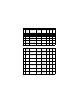
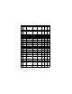
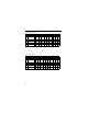
No. Name Unit Factory setting
– Inverter capacity kW 0.1kW 0.25kW 0.55kW 1.1kW 1.5kW 2.2kW – 3.7kW 5.5kW 7.5kW
n036 Motor rated current A 0.6 1.1 1.9 3.3 6.2 8.5 – 14.1 19.6 26.6
n105
Torque
compensation iron
loss
W 1.7 3.4 4.2 6.5 11.1 11.8 – 19 28.8 43.9
n106 Motor rated slip Hz 2.5 2.6 2.9 2.5 2.6 2.9 – 3.3 1.5 1.3
n107
Motor resistance for
one phase*
Ω
17.99 10.28 4.573 2.575 1.233 0.8 – 0.385 0.199 0.111
n108
Motor leakage
inductance
MH 110.4 56.08 42.21 19.07 13.4 9.81 – 6.34 4.22 2.65
n110
Motor no-load
current
% 72 73 62 55 45 35 – 32 26 30