
Instruction Manual

153
• Recommended Peripheral Devices
It is recommended that the following peripheral devices should be mounted between
the AC main circuit power supply and VS-606V7 input terminals R/L1, S/L2, and T/
L3.
• MCCB (Molded-case circuit breaker)/fuse:
Be sure to connect it for wiring protection.
• Magnetic contactor:
Mount a surge suppressor on the coil (refer to the table shown below).
When using a magnetic contactor to start and stop the inverter, do not exceed one
start per hour.
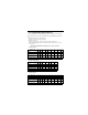
Recommended MCCB and magnetic contactor, and fuse
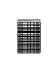
• 200V 3-phase
• 200V single-phase
• 400V 3-phase
VS-606V7 model
V7
∗ ∗
20P1
V7
∗ ∗
20P2
V7
∗ ∗
20P4
V7
∗ ∗
20P7
V7
∗ ∗
21P5
V7
∗ ∗
22P2
V7
∗ ∗
23P7
V7
∗ ∗
25P5
V7
∗ ∗
27P5
Capacity (kVA) 0.3 0.6 1.1 1.9 3.0 4.2 6.7 9.5 13.0
Rated Output Current (A) 0.8 1.6 3 5 8 11 17.5 25.0 33.0
MCCB type NF30
(MITSUBISHI)
5A 5A 5A 10A 20A 20A 30A 50A 60A
Magnetic contactor type HI
(YASKAWA CONTROL)
HI-7E HI-7E HI-7E HI-7E HI-10-2E HI-10-2E HI-20E HI-30E HI-50E
Fuse (UL Class RK5) 5A 5A 5A 10A 20A 20A 30A 50A 60A
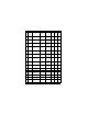
VS-606V7 model
V7
∗ ∗
B0P1
V7
∗ ∗
B0P2
V7
∗ ∗
B0P4
V7
∗ ∗
B0P7
V7
∗ ∗
B1P5
V7
∗ ∗
B2P2
V7
∗ ∗
B3P7
Capacity (kVA) 0.3 0.6 1.1 1.9 3.0 4.2 6.7
Rated Output Current (A) 0.8 1.6 3 5 8 11 17.5
MCCB type NF30, NF50
(MITSUBISHI)
5A 5A 10A 20A 20A 40A 50A
Magnetic contactor type HI
(YASKAWA CONTROL)
HI-7E HI-7E HI-7E HI-10-2E HI-15E HI-20E HI-30E
Fuse (UL Class RK5) 5A 5A 10A 20A 20A 40A 50A
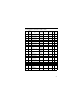
VS-606V7 model
V7
∗ ∗
40P2
V7
∗ ∗
40P4
V7
∗ ∗
40P7
V7
∗ ∗
41P5
V7
∗ ∗
42P2
V7
∗ ∗
43P0
V7
∗ ∗
44P0
V7
∗ ∗
45P5
V7
∗ ∗
47P5
Capacity (kVA) 0.9 1.4 2.6 3.7 4.2 5.5 7.0 11.0 14.0
Rated Output Current (A) 1.2 1.8 3.4 4.8 5.5 7.2 9.2 14.8 18.0
MCCB type NF30, NF50
(MITSUBISHI)
5A 5A 5A 10A 10A 20A 20A 30A 30A
Magnetic contactor type HI
(YASKAWA CONTROL)
HI-7E HI-7E HI-7E HI-10-2E HI-10-2E HI-10-2E HI-10-2E HI-20E HI-20E
Fuse (UL Class RK5) 5A 5A 5A 10A 10A 20A 20A 30A 30A