
Instruction Manual


147
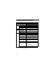
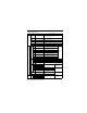
Terminal Description
* DC power supply input terminal is not applied to CE/UL standards.
‡
Can be switched to pulse monitor output.
Type Terminal Name Function (Signal Level)
Main Circuit
R/L1,
S/L2,
T/L3
AC power supply input
Always use terminal R/L1, S/L2 for single-phase
inverters.
Never connect to terminal T/L3.
U/T1,
V/T2,
W/T3
Inverter output Inverter output
B1, B2 Braking resistor connection Braking resistor connection
+2, +1 DC reactor connection
When connecting optional DC reactor, remove the main
circuit short-circuit bar between +2 and +1.
+1, (–) DC power supply input DC power supply input (+1: positive –: negative)*
Grounding
Grounding 200V: ground to local grounding codes
400V: ground to local grounding codes
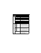
Control Circuit
Input
Sequence
S1
Multi-function input selection 1
Factory setting closed: FWD run, open:
REV run
Photo-
coupler
insulation
24VDC,
8mA.
S2
Multi-function input selection 2
Factory setting closed: REV run, open:
FWD run
S3
Multi-function input selection 3
Factory setting: External fault (NO
contact)
S4
Multi-function input selection 4
Factory setting: Fault reset
S5
Multi-function input selection 5
Factory setting: Multi-step speed
reference 1
S6
Multi-function input selection 6
Factory setting: Multi-step speed
reference 2
S7
Multi-function input selection 7
Factory setting: Jog reference
SC
Multi-function input selection common
For control signal
Frequency reference
RP
Master speed reference pulse
train input
33kHz max.
FS Power for frequency setting +12V (permissible current 20mA max.)
FR
Master speed frequency reference
0 to +10VDC (20k
Ω
) or 4 to 20mA (250k
Ω
) or 0 to 20mA (250
Ω
) (1/1000
resolution)
FC
Frequency reference
common
0V
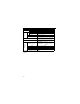
Output
Multi-function contact output
MA NO contact output
Factory setting: fault
Contact capability
250VAC 1A or less,
30VDC 1A or less
MB NC contact output
MC Contact output common
P1 Photo-coupler output 1 Factory setting: Run
Photo-coupler output
+48VDC, 50mA or less
P2 Photo-coupler output 2
Factory setting: Frequency
agreed
PC
Photo-coupler output
common ‡
0V
AM Analog monitor output
Factory setting:
Output frequency 0 to +10V
+10VDC, 2mA or less,
8-bit resolution
AC Analog monitor common 0V
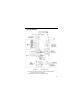
Communication
Circuit Terminal
MEMOBUS
communications
R+ Communications input (+)
MEMOBUS communication
Run through RS-485 or
RS-422.
RS-485/422
MEMOBUS protocol,
19.2 kps max.
R- Communications input (-)
S+ Communications output (+)
S- Communications output (-)