
Instruction Manual


142
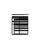
• Standard Specifications (400V Class)
Voltage Class 400V 3-phase
Model
CIMR-V7*C
‰‰‰‰
3-phase 40P2 40P4 40P7 41P5 42P2 43P0 43P7 45P5 47P5
Single-phase – – – ––––––
Max. Applicable Motor Output HP
(kW)*
0.5
(0.2)
0.75
(0.4)
2
(0.75)
3
(1.5)
3
(2.2)
3
(3.0)
5
(3.7)
7.5
(5.5)
10
(7.5)
Output
Characteristics
Inverter Capacity (kVA) 0.9 1.4 2.6 3.7 4.2 5.5 7.0 11 14
Rated Output Current (A) 1.2 1.8 3.4 4.8 5.5 7.2 9.2 14.8 18
Max. Output Voltage (V) 3-phase, 380 to 460V (proportional to input voltage)
Max. Output
Frequency (Hz)
400 Hz (Programmable)
Input
Current (A)
(3-Phase) 1.6 2.4 4.7 7.0 8.1 10.6 12.0 19.6 23.8
Power
Supply
Rated Input Voltage
and Frequency
3-phase, 380 to 460V, 50/60Hz
Allowable Voltage
Fluctuation
-15 to +10%
Allowable Frequency
Fluctuation
±
5%
Control Characteristics
Control Method Sine wave PWM (V/f control/voltage control selectable)
Frequency Control Range 0.1 to 400Hz
Frequency Accuracy
(Temperature Change)
Digital reference:
±
0.01%, 14 to 122
°
F (-10 to +50
°
C)
Analog reference:
±
0.5%, 59 to 95
°
F (25
±
10
°
C)
Frequency Setting Resolution
Digital reference: 0.01Hz (less than 100Hz) / 0.1Hz (100Hz
or more)
Analog reference: 1 / 1000 of max. output frequency
Output Frequency
Resolution
0.01Hz
Overload Capacity 150% rated output current for one minute
Frequency Reference
Signal
0 to 10VDC (20k
Ω
), 4 to 20mA (250
Ω
), 0 to 20mA (250
Ω
)
pulse train input, frequency setting potentiometer
(Selectable)
Accel/Decel Time
0.00 to 6000 sec. (accel/decel time are independently
programmed)
Braking Torque
Short-term average deceleration torque‡
0.2kW: 150%
0.75kW: 100%
2HP (1.5kW): 50%
3HP (2.2kW) or more: 20%
Continuous regenerative torque: Approx. 20% (150% with
optional braking resistor, braking transistor built-in)
V/f Characteristics Possible to program any V / f pattern
* Based on a standard 4-pole motor for max. applicable motor output.
‡
Shows deceleration torque for uncoupled motor decelerating from 60Hz
with the shortest possible deceleration time.