MCP Process PumpenAntrieb Pump drive Moteur de pompe Mikroprozessorgesteuert Microprocessor controlled Commandé par microprocesseur Schutzgrad IP 65 Protection rating IP 65 Classe de protection IP 65 ISM 915 ISM 915 ISM 915 Für Pumpenköpfe: Pro 280 / Pro 281 Pro 380 / Pro 381 360 / 380 / 380 AD CA 4 / CA 8 / CA 12 FMI Q0 / Q1 / Q2 / Q3 Easy-Load Standard Quickload MS 3 MS/CA 4-12 / MS/CA 8-6 PTFE Membran HF/LF PTFE Tube 2 mm / 4 mm SB 2V / 3V / 5V SB 2V LP WM 5 For pump-heads: Pro 280 / Pro 28
Inhaltsverzeichnis Sicherheitsvorkehrungen 2 Contents 4–5 Safety precautions Sommaire 4–5 Mesures de précaution 4–5 Garantiebestimmungen 6 Warranty terms 6 Conditions de garantie 6 Produkt Geräterückwand Netzspannung 7 8 8 Product Rear panel Mains voltage 7 8 8 Produit Tableau arrière Tension d’alimentation 7 8 8 Inbetriebnahme Bedienungspanel 9 10 Starting the pump Operating panel 9 10 9 10 Start-Information 11 Start-up information 11 Mise en route Tableau de commande Informatio
Inhaltsverzeichnis Sommaire Intervall-Dosieren nach Zeit nach Volumen 25 26 Intermittent dispensing by time by volume 25 26 Anzahl Dosierzyklen Tropfenfreies Dosieren 27 28 No.
Hinweis Wir empfehlen, diese Betriebsanleitung genau durchzulesen. Ismatec SA haftet nicht für Schäden, die durch unsachgemäße Handhabung des Antriebs MCP Process entstehen. Beim Betrieb einer Pumpe sind gewisse Gefahren nicht auszuschließen. Ismatec SA übernimmt keine Haftung für daraus resultierende Schäden. Sicherheitsvorkehrungen ® Die Ismatec Pumpen sind für Förderzwecke in Labors und der Industrie vorgesehen.
Restrisiken Der Umgang mit Chemikalien liegt nicht im Verantwortungsbereich der Ismatec SA. General risks Sicherheitsvorkehrungen Manipulieren Sie nicht am Pumpenkopf, bevor die Pumpe ausgeschaltet und vom Netz getrennt ist. ■ Do not manipulate the pumphead before the pump is switched off and disconnected from the mains supply. ■ ■ Achten Sie besonders darauf, dass keine Körperteile wie Finger, Haare, usw. oder Schmuck sowie lose Gegenstände wie Kabel, Schläuche, usw.
b Garantie ® Auf allen von Ismatec hergestellten Erzeugnissen ab Lieferdatum: 2 Jahre Übrige Teile, ohne Verschleißmaterial: 1 Jahr Bei Unklarheiten wenden Sie sich bitte an Ihre Ismatec®-Vertretung. b Warranty For all parts manufactured by Ismatec® from date of delivery: 2 years All other parts, excluding consumables: 1 year In case of any queries, please contact your Ismatec® representative.
Produkt Product Produit Packungsinhalt Contents of the package Emballage ■ Antrieb MCP Process Bestell-Nr. ISM 915 inkl. fest montiertem Netzkabel Länge 2 m, mit Gerätekupplung IEC 320 (male) ■ MCP Process drive Order No. ISM 915 incl.
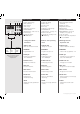
1 2 5 Geräterückwand Rear panel Tableau arrière 1 Netzschalter (ein/aus) 1 Mains switch (on/off) 1 Interrupteur principal 2 Netzkabel 2 Power cord 2 Prise d’alimentation 4 3 RS232 IN (Eingang, weiblich) 3 RS232 IN (female) 4 RS232 OUT (Ausgang, männlich) 4 RS232 OUT (male) 3 RS232 IN (entrée femelle) 4 RS232 OUT (sortie mâle) 3 5 Analog-Schnittstelle ■ Eingänge für: - Drehzahlsteuerung 0–5 V oder 0–10 V, bzw.
Inbetriebnahme ■ Pumpenkopf gemäß separater Montageanleitung für Pumpenköpfe montieren ■ ID-Codes der verwendeten Pumpenköpfe in die entsprechend benutzten Programmspeicher eingeben (siehe Seite 14 und 46) Cummutateur principal sur tableau arrière MCP Process/Ismatec SA/30.07.
1 2 3 9 TUBE I.D.
1 2 3 4 Start-Information Start-up information Informations de mise en route Die folgenden Einstellungen leuchten nach dem Einschalten des Netzschalters kurz auf: After switching on the power supply switch, the following values are displayed: Les réglages suivants s’illuminent brièvement après la mise en route de l’interrupteur de réseau: 1 LED-Test »8.8.8.8.« 1 LED test »8.8.8.8.« 1 Test LED »8.8.8.8.
aus off 1 MODE 2 Die Parameter des aktuellen Programms auf ihre Default-Werte setzen. Resetting the parameters of the currently used program to the default values. Remise des paramètres du programme actuel à leurs valeurs par défaut.
a b RUN STOP MODE TUBE I.D. PUMP DISP PAUSE mm rpm Time Time c d CAL e f PROGRAM Flow rate Volume TOTAL Steuertasten Control keys Touches de commande a RUN/STOP Pumpe starten bzw. stoppen a RUN/STOP Starts and stops the pump b MODE Wechselt zwischen den Betriebsarten (siehe Seite 10) b MODE Changes between operating modes (see page 10) c Drehrichtung Wechselt die Drehrichtung. ❖ Diese Funktion ist beim Membran-Pumpenkopf blockiert.
aus off 1 2 ein on CAL 3 Pumpenkopf-Identifikation Pump-head identification Identification de la tête de pompe Für korrekte Pump- und DosierWerte muss die richtige Pumpenkopf-Identifikation (ID-Code) des jeweils montierten Pumpenkopfes gespeichert werden ( für jedes der 4 Programme). Vor allem bei der ersten Inbetriebnahme und nach jedem Wechsel eines Pumpenkopfes.
1 2 MODE TUBE I.D. PUMP DISP PAUSE mm rpm Time Time PROGRAM Flow rate Volume TOTAL CAL iØ i.d. Ø int. 3a Peristaltik-Pumpenkopf Peristaltic pump-head Tête péristaltique Winkel Angle 3b Kolben-Pumpenkopf Piston pump-head Tête piston 4 5 CAL MCP Process/Ismatec SA/30.07.00/CB/GP Schlauch-Innendurchmesser oder Hubwinkel eingeben Entering the tubing i.d.
MODE 1 2 TUBE I.D. PUMP DISP PAUSE mm rpm Time Time PROGRAM Flow rate Volume TOTAL CAL Programmwahl Program selection Sélection du programme Beim Einschalten wählt die Pumpe immer das zuletzt benutzte Programm. When switching the pump on, it always selects the previously used program. Lors de l’enclenchement de la pompe, cette dernière choisit toujours le dernier programme utilisé. 1 Mit der MODE-Taste in Modus PROGRAM wechseln. 1 Change mode to PROGRAM by using the MODE-key.
1 MODE TUBE I.D. PUMP DISP PAUSE mm rpm Time Time RUN STOP 2 Pumping by drive speed Pompage selon le nombre de tours 1 Mit der MODE-Taste auf PUMP rpm, 1.0–240.0 min–1, einstellbar in Schritten von 0.1 min–1 1 Change mode to PUMP rpm, 1.0–240.0 rpm, adjustable in steps of 0.1 rpm 1 Passer sur PUMP rpm avec la touche MODE, 1.0–240.0 t/min., réglable par pas de 0.1 t/min.
1 MODE TUBE I.D. PUMP DISP PAUSE mm rpm Time Time PROGRAM Flow rate Volume TOTAL RUN STOP 2 z.B.12.5µl/min (siehe auch S. 21) e.g.12.5µl/min (see also page 21) p.e.12.5µl/min (voir page 21) Pumping by flow rate Pompage selon le débit 1 Mit der MODE-Taste auf PUMP Flow rate 1 Change mode to PUMP Flow rate 1 Passer avec la touche MODE sur PUMP Flow rate 2 Mit den Tasten gewünschte Fließrate wählen (wird in µl/min bzw.
1 2 MODE MODE TUBE I.D. PUMP DISP PAUSE TUBE I.D. PUMP DISP PAUSE mm rpm Time Time mm rpm Time Time PROGRAM Flow rate Volume TOTAL PROGRAM Flow rate Volume TOTAL RUN STOP 3 4 5 MODE TUBE I.D.
1 MODE 2 RUN 3 STOP TUBE I.D. PUMP DISP PAUSE mm rpm Time Time PROGRAM Flow rate Volume TOTAL Dosieren nach Zeit Dispensing by time Dosage selon le temps Die Dosierzeit kann von 0.1s–999h eingegeben werden. The dispensing time can be entered from 0.1s to 999h. La durée de dosage peut être définie entre 0.
1 MODE TUBE I.D. PUMP DISP PAUSE mm rpm Time Time PROGRAM Flow rate Volume TOTAL Dosieren nach Volumen Dispensing by volume Dosage selon le volume 1 Mit der MODE-Taste auf DISP Volume 1 Change mode to DISP Volume 1 Passer avec la touche MODE sur DISP Volume 2 Mit den Tasten gewünschtes Dosiervolumen eingeben. Drei DisplayAnzeigen sind möglich: 2 Use the keys for entering the required dispensing volume.
1 MODE RUN 2 STOP 3 CAL mm rpm Time Time PROGRAM Flow rate Volume TOTAL Volumen kalibrieren Calibrating the volume Calibration du volume 1 Mit MODE-Taste auf DISP Volume ❖ Mit den Tasten das Dosiervolumen eingeben 1 Change MODE to DISP Volume ❖ Use the keys for entering the required dispensing volume 2 Start with RUN/STOP ❖ Pump stops automatically ❖ The pump reduces the rotation speed shortly before the end of the dispensing cycle providing controllable and dropprecise dispensing volumes ❖
1 2 MODE TUBE I.D.
1 2 3 MODE MODE MODE TUBE I.D. PUMP DISP PAUSE mm rpm Time Time PROGRAM Flow rate Volume TOTAL TUBE I.D. PUMP DISP PAUSE mm rpm Time Time PROGRAM Flow rate Volume TOTAL TUBE I.D. PUMP DISP PAUSE mm rpm Time Time PROGRAM Flow rate Volume TOTAL TUBE I.D.
1 MODE TUBE I.D. PUMP DISP PAUSE mm rpm Time Time PROGRAM Flow rate Volume TOTAL Intervall-Dosieren (Zeiteinheit) Intermittent dispensing (by time) Repetitives Dosieren nach Zeit mit vorgegebener Pausenzeit Intermittent dispensing by time Dosage répétitif selon le temps with a pre-set pause time avec un temps de pause prédéfini. 1 Go to mode PAUSE Time 1 Passer avec la touche MODE • Enter the pause time sur PAUSE Time (between 0.
Intervall-Dosieren (Volumen) 1 2 MODE MODE TUBE I.D. PUMP DISP PAUSE mm rpm Time Time PROGRAM Flow rate Volume TOTAL TUBE I.D. PUMP DISP PAUSE mm rpm Time Time PROGRAM Flow rate Volume TOTAL RUN 3 STOP Hinweis Einstellung Anzahl Dosieryklen siehe Seite 28 Please note For entering the number of dispensing cycles see page 28. Remarque Pour programmer le nombre de cycles de dosage voir page 28.
1 2 MODE TUBE I.D. PUMP DISP PAUSE mm rpm Time Time PROGRAM Flow rate Volume TOTAL TUBE I.D. PUMP DISP PAUSE mm rpm Time Time PROGRAM Flow rate Volume TOTAL CAL Anzahl Dosierzyklen Number of dispensing cycles Nombre de cycles de dosage Beim Dosieren in Intervallen (nach Zeit bzw. Volumen) kann die Anzahl Dosierzyklen vorgegeben werden. The number of dispensing cycles can be entered when dispensing at intervals (by time and volume). Lors du dosage par intervalles (selon le temps, resp.
aus off couper le contact 1 ein on mettre le contact 2 Tropfenfreies Dosieren Drip-free dispensing Dosage sans goutte Mit programmierbaren Rollenrückschritten bzw. KolbenhubRückschritten (beim FMI Pumpenkopf) (1–100 Schritte bzw. Hübe) With programmable roller backsteps or piston stroke back-steps (FMI pump-head) (1–100 steps or strokes) Avec des pas arrière programmables (des galets ou des courses de pistons {tête de pompe FMI}) (1–100 pas, resp.
Hinweis Pumpen gegen Druck Pumping against pressure Druckregelungs-Einheit siehe Seite 42. Die MCP Process kann im Dauerbetrieb bis max. 1.5 bar Differenzdruck eingesetzt werden. Je nach Pumpenkopf und Schlauchdurchmesser (kleinere Durchmesser) kann kurzzeitig auch gegen einen höheren Druck gepumpt werden. The MCP Process can be used for continuous duty at a differential pressure of max. 1.5 bar.
Überlastschutz Overcurrent protector Protection de surcharge Der Antrieb MCP Process verfügt über eine Überlast-Sicherung. Eine Überlastung wird im Display durch die Buchstaben „OL“ (für „Overload“) angezeigt, und die Pumpe stoppt. The drive MCP Process features a an overload protector. When an overload condition occurs, it is indicated in the display by the letters 'OL' and the pump is stopped. La pompe IP possède une protection de surcharge.
Hinweis Einlaufzeit der Schläuche Running-in period for tubing Durée de rodage des tubes Wir verweisen auf unsere ausführliche Schlauchdokumentation. Jeder neue Schlauch braucht eine Einlaufzeit. Every new tube requires a running-in period. Chaque nouveau tube a besoin d’un temps de rodage Für konstante und reproduzierbare Fließraten ist es unbedingt nötig, neue Schläuche vor ihrem Einsatz mind. 1–3 Stunden mit Wasser oder dem zu fördernden Medium einlaufen zu lassen.
speed IN input 1 +26VDC input 2 direction start remote GND 8 7 6 5 4 3 21 15 14 13 12 11 10 9 output 2 speed OUT output 1 speed intern +5VDC Digitale Eingänge (TTL-Pegel) Digital inputs (TTL-level) Entrées numériques (niveau TTL) Pin 2, remote Pin 3, start Pin 4, direction Pin 6, input 1 Pin 8, input 2 Pin 13, speed intern Analoge Eingänge Analog inputs Entrées analogiques Pin 5, speed IN 0–5 VDC / 0–10 VDC 0–20 mA / 4–20 mA Universal Ausgänge (PWM) Universal outputs (PWM) Sorties universelles (PWM) P
speed IN input 1 +26VDC input 2 direction start remote GND 8 7 6 5 4 3 21 15 14 13 12 11 10 9 output 2 speed OUT output 1 speed intern +5VDC Digitale Eingänge (TTL-Pegel) Digital inputs (TTL-level) Entrées numériques (niveau TTL) Pin 2, remote Pin 3, start Pin 4, direction Pin 6, input 1 Pin 8, input 2 Pin 13, speed intern Analoge Eingänge Analog inputs Entrées analogiques Pin 5, speed IN 0–5 VDC / 0–10 VDC 0–20 mA / 4–20 mA Universal Ausgänge (PWM) Universal outputs (PWM) Sorties universelles (PWM) P
Einstellungen Schalter S1 A S2 S1 Fußschalter-Betrieb Mit DIP-Switch 5 kann zwischen zwei Möglichkeiten gewählt werden: - »FS toggle« (Ein/Aus) - »FS direct« (Ein = solange Fußschalter gedrückt bleibt) ❖ B DIP-Switch Eingang Input / Entrée Pin 9 Ausgang Output/Sortie A = 0–10 VDC (Standard) B = 0–7.
Hinweis Serielle Schnittstelle Serial interface Interface sérielle Der Antrieb MCP Process hat beim Einschalten eine Verzögerung von 3 Sekunden, bis die serielle Schnittstelle zuverlässig anspricht. RS232 IN (Eingang, weiblich) Der Anschluss erfolgt über eine 9-polige D-Buchse. RS232 IN (female) A 9-pin D-socket is available on the rear panel of the pump. RS232 IN (entrée femelle) Le raccordement se fait par le biais d’une douille D à 9 pôles (femelle).
Serielle Schnittstelle / Serial interface / Interface sérielle Pumpensoftware Version Pump software version Version du logiciel de la pompe 1.01 Microsoft Windows Visual Basic kann zur Programmierung der nachstehenden Befehle angewendet werden. can be used for programming the following commands. peut-être utilisé pour la programmation des commandes suivantes.
Serielle Schnittstelle / Serial interface / Interface sérielle Befehl Funktion / Beschreibung Command Function / Description Commande Fonction / Description D_ _ _ _ _ Zahlen für Bedienfeld schreiben (nur bei inaktivem Bedienfeld sichtbar, siehe Befehl B) Writing numbers for control panel (only visible if control panel is inactive, see command B) Ecrire les chiffres pour le panneau de commande (visible uniquement lorsque le panneau est inactif, voir commande B) DA_ _ _ _ Buchstaben (Text) für Bedienfeld sch
Serielle Schnittstelle / Serial interface / Interface sérielle Befehl Funktion / Beschreibung Command Function / Description Commande Fonction / Description +_ _ _ _ S S_ _ _ _ _ ? Eingabe: Input: Saisie: Abfrage: Inquiry: Interrogation: Eingabe: Input: Saisie: Abfrage: Inquiry: Interrogation: ! !_ _ _ _ Abfrage: Inquiry: Interrogation: Eingabe: Input: Saisie: [ V V_ _ _ _ VM_ _ _ VH_ _ _ U U_ _ _ _ Abfrage: Inquiry: Interrogation: Abfrage: Inquiry: Interrogation: Eingabe: Input: Saisie: Eing
Serielle Schnittstelle / Serial interface / Interface sérielle Befehl Funktion / Beschreibung Command Function / Description Commande Fonction / Description [_ _ _ _ _ Eingabe: Input: Saisie: % %____ T T_ _ _ _ TM _ _ _ TH _ _ _ " "____ : W * 0 Abfrage: Inquiry: Interrogation: Eingabe: Input: Saisie: Abfrage: Inquiry: Interrogation: Eingabe: Input: Saisie: Eingabe: Input: Saisie: Eingabe: Input: Saisie: Abfrage: Inquiry: Interrogation: Eingabe: Input: Saisie: Abfrage: Inquiry: Interrogation:
Serielle Schnittstelle / Serial interface / Interface sérielle Befehl Funktion / Beschreibung Command Function / Description Commande Fonction / Description \000_ \0000 .
max. 8 Pumpen / pumps / pompes PC RS232 in out RS232 in out RS232 in out Jede Pumpe braucht eine eigene Adresse. (siehe Seite 35). Each pump requires an individual address. (see page 35). Chaque pompe doit disposer d’une adresse qui lui est propre. (voir page 35) MCP Process/Ismatec SA/30.07.00/CB/GP Kaskadierung mehrerer Pumpen Cascading several pumps Montage en cascade de plusieurs pompes Sofern Sie über eine entsprechende Software verfügen, können bis max.
SOF104 ProgEdit Demo Version: www.ismatec.com SOF103 Labworldsoft ❖ ❖ Verlangen Sie nähere Software-Unterlagen. ❖ ❖ Please ask for more detailed software-information. ❖ ❖ Demandez-nous de plus amples informations à ces sujets. 42 Programmier-Software Programming Software Logiciel de programmation Software ProgEdit ■ Kreieren Sie Ihre individuelle Programm-Applikation am PC. ■ Laden Sie diese via RS232Schnittstelle in Ihre MCP Process.
IM0015C168 Moxa C168 max. 8 Pumpen pumps pompes 0.5 m XC0009 Adapter Adaptateur 25 F / 9 M AG0013 9F 9M (2 m) Zubehör Accessories Accessoires Schnittstellenkarte Moxa C168 inkl. 25 poliges (male) Mehrfachkabel zur Steuerung von max. 8 Laborgeräten Bestell-Nr. IM0015C168 nterface card Moxa C168 including a 25 pin multiple cable (male) for controlling up to 8 laboratory instruments Order No.
MS/CA Click‘n‘go Kassette MS/CA Click‘n‘go cassette 3-Stopper-Schläuche 3-stop collared tubing Tubes à 3 arrêts CA Click‘n‘go Kassette CA Click‘n‘go cassette Zubehör Accessories Accessoires Ersatz-Kassetten aus POM MS/CA Click'n'go Bestell-Nr. IS 3510 Spare-cassettes in POM MS/CA Click'n'go Order No. IS 3510 Cassettes de rechange en POM MS/CA Click'n'go No de commande IS 3510 MS/CA Anpresshebel* Bestell-Nr. IS 0649 MS/CA pressure lever* Order No.
Montage Jedem Pumpenkopf liegt eine Montageanleitung bei. Vor Inbetriebnahme den korrekten ID-Code eingeben (siehe Seite 14 und 46). Mounting Each pump-head is supplied with an instruction manual. Do not forget to enter the correct ID code (see page 14 and 46) Montage Auswechselbare Pumpenköpfe Diese Pumpenköpfe können einzeln bestellt und am Antrieb MCP-Standard montiert werden. ❖ ❖ Bei den Taumelkolbenköpfen bedeutet die Nachsilbe „-W“ resp.
ID-No.: Pumpenkopf-Identifikation / Pump-head identification / Identification des têtes de pompe Muss in allen mit dem jeweiligen Pumpenkopf Must be entered for each of the 4 programs Doit être saisi dans tous les programmes verwendeten Programmen eingegeben werden. Rollen Rollers Gallets Schlauch/Kolben Tubing/piston Tube/piston iØ I.D. / Ø int. mm WS WT Paroi 1.6 Fließ raten Flow rates / Débit min. (ml/min) max 360 360 719 ISM 719 0.08 880 1 3 Standard 0.8 – 6.
Hinweis Bei den Angaben in den nachfolgenden Tabellen handelt es sich nur um Richtwerte, die wie folgt ermittelt wurden: ml/min, pro Kanal, mit Wasser und Tygon®-Schlauch, ohne Differenzdruck Für die Auswahl des Schlauchmaterials sind wir gerne behilflich. Die Verantwortung für die richtige Wahl liegt jedoch beim Benutzer.
Typ/Type SB 2V SB 3V SB 2LP 360 380 380 AD Pro-280 Pro-281 Channels/Canaux Pumpenkanäle 2 3 - 1 1 1 1 1 Pumpenrollen Rollers/Gallets 6 6 - 3 3 3 2 2 Meterware Standard Tubing Tubes au mètre Meterware Standard Tubing Tubes au mètre In Vorbereitung In preparation En préparation Meterware Standard Tubing Tubes au mètre Meterware Standard Tubing Tubes au mètre Meterware Standard Tubing Tubes au mètre Meterware Standard Tubing Tubes au mètre Meterware Standard Tubing Tubes au m
Hinweis Bei den Angaben in den nachfolgenden Tabellen handelt es sich nur um Richtwerte, die wie folgt ermittelt wurden: ml/min, pro Kanal, mit Wasser und Tygon®-Schlauch, ohne Differenzdruck Für die Auswahl des Schlauchmaterials sind wir gerne behilflich. Die Verantwortung für die richtige Wahl liegt jedoch beim Benutzer.
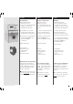
Öffnen der Gehäusehaube Opening the casing hood Ouverture du boîtier Um die Dichtigkeit des In order to maintain the best Gehäuses zu gewährleisten, empfehlen wir, die Pumpe nur für das Ersetzen einer Sicherung oder zum Ändern einer DIP-SwitchEinstellung zu öffnen. Es ist wie folgt vorzugehen: possible seal of the casing, the pump should only be opened for replacing the fuses or changing the DIP-switches.
Öffnen der Gehäusehaube 2 1 MCP Process/Ismatec SA/30.07.00/CB/GP Opening the casing hood Ouverture du boîtier Abdichten der Haube Sealing the casing hood Wenn die Haube gut sitzt, muss When the casing hood fits tight, jede Schraube (einzeln!) erneut each single screw must be herausgedreht und mit Silikonremoved again and stopped with Dichtungsmasse abgedichtet silicone sealing compound. Then, werden.
a b Auswechseln der Sicherungen Changing the fuses Remplacement des fusibles Die Sicherungen sind auf dem Steuerprint (oben) und auf dem Netzteilprint (unten) wie nebenstehend abgebildet angebracht. The fuses are fixed to the control board (above) and the power supply print (below) as illustrated opposite. Les fusibles sont fixés sur le tableau de commande (dessus) et sur le tableau réseau (dessous) conformément à la photo cicontre. Absicherung Steuerprint a 4.0 A, träge b 1.
Unterhalt Maintenance Maintenance Sofern die MCP Process bestimmungsgemäß und mit der nötigen Sorgfalt eingesetzt wird, unterliegt lediglich das Schlauchmaterial einem gewissen Verschleiß. Provided the MCP Process is operated properly and in compliance with this manual, the tubing is the only part that is subject to wear and tear.
Hinweis Beachten Sie ebenfalls unsere Garantie- und allgemeinen Verkaufs- und Lieferbedingungen. Bitte setzen Sie sich bei Fragen oder Unklarheiten mit Ihrer lokalen Ismatec®-Vertretung in Verbindung. Please note We also recommend you to observe our Warranty Terms as well as our Terms and Conditions of Sale. In case of any queries, please contact your local Ismatec® representative.
Kurzanleitung Program selection / Programm wählen Quick Start Instruction The Quick Start Instruction on your right helps you control the pump instantly. Thanks to an adhesive foil, this instruction sheet can be stuck to the casing hood of your pump. Mode d’emploi abrégé Vous trouverez ci-contre un mode d’emploi abrégé sur feuille autocollante. Pour que vous ayez toujours le mode d’emploi sous la main, vous pouvez le coller sur le boîtier de votre pompe.
Ismatec® - Vertretung Representative/Représentation ISMATEC SA Labortechnik - Analytik A Unit of IDEX Corporation Feldeggstrasse 6 P.O. Box CH-8152 Glattbrugg-Zürich Switzerland Phone Fax E-Mail Internet +41 (0)1 874 94 94 (0)1 810 52 92 sales@ismatec.ch www.ismatec.