
User's Manual
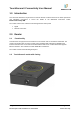
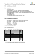
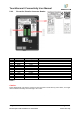
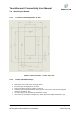
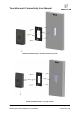
Table Of Contents

TouchSecure® Connectivity User Manual
IDT.QM.P2.T1.DT
Ver1.0
Page 6 of 11
Printed copies of this document are uncontrolled
Internal Use Only
5.0 Installation details
5.1 Parts List
• TouchSecure® reader -1
• Screws (A #6-18X1.5" SS ) - 4Nos – Back Plate mounting screws for Wall
• Snake Eye Screw (SMF #6-32X5/16" SS) – 1 No- Top casing mounting security screw
• Screws (SMF #6-32x3/8" SS) - 3 No’s - 1 casing to back plate mounting screw and 2 Junction
Box mounting screws
• Nylon anchor plug -4 Nos
• 6 pin phoenix plug (Phoenix connector version only) – 2 Nos
• Back Plate
5.2 Recommended Infrastructure
• Cable Wiegand - 22AWG for 500Ft / 24AWG for 300Ft with Foil Shield
• Cable RS485 - RS485 for 1000m** (4000ft) 24AWG STP
• Cable RJ45 - Cat5e / Cat6
• Linear DC PS - 5-16 V, 1A min.
• POE Adaptor Kit - TL-POE200A
** Tested in lab conditions upto 115Kbaud
5.3 Wiring Information
5.3.1 Cable Color codes for Pig Tail Reader
Red
&
+ VDC 12V (nominal)
Black & White
Ground
Green
Wiegand Data 0
White
Wiegand Data 1
Orange
LED Green
Yellow
Buzzer
Blue
Hold
Brown
LED Red
Grey
RS485 -
Pink
RS 485 +
Violet
Tamper Output
Black / Drain
Shield Ground
Table 2
& -
Do not connect when reader is powered by Power over Ethernet