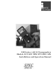
ILR Series i-Q310 Transponders Models CST/SET/ATR/LPT/DRT/ATN Installation and Operation Manual
i-Q 310 ISO 18000-7 Transponder Series Proprietary Notice This document contains confidential information proprietary to IDENTEC SOLUTIONS and may not be used or disclosed to other parties in whole or in part without prior written authorization from IDENTEC SOLUTIONS.
i-Q 310 ISO 18000-7 Transponder Series Radio Frequency Compliance Statement IDENTEC SOLUTIONS is the responsible party for the compliance of the following devices: MODELS: EUROPE: USA Canada i-Q310 CST, i-Q310 SET, i-Q310 ATR, i-Q310 LPT, i-Q310, i-Q310 DRT, i-Q310 ATN CE FCC, HERO Industy Canada FCC ID OO4-IQ310 for Models i-Q310 SET, i-Q310 ATR, i-Q310 LPT, i-Q310 DRT FCC ID OO4-IQ310CST for Model i-Q310 CST FCC ID OO4-IQ310ATN for Model i-Q310 ATN Industry Canada: IC:3538A-IQ310 for Models i-Q310 SET,
i-Q 310 ISO 18000-7 Transponder Series Safety Precautions Important Safety Notes The system described in this manual is for exclusive operation by trained employees. Only qualified personnel that know the potential dangers involved should perform the installation, settings, maintenance and repair of the units used. On account of high operating temperature of 80°C (+176°F) care must be taken, if the tags are heated. To avoid burn wait a while until the tags have cooled down or use gloves.
i-Q 310 ISO 18000-7 Transponder Series Page 5 of 23
i-Q 310 ISO 18000-7 Transponder Series Contents 1 INTRODUCTION ........................................................................................................... 7 1.1 1.2 I-Q310 SERIES TRANSPONDER FUNCTIONALITY .................................................................. 7 CST AND SET FEATURES AND BENEFITS ........................................................................... 7 2 TECHNICAL SPECIFICATIONS..............................................................................
i-Q 310 ISO 18000-7 Transponder Series 1 Introduction 1.1 i-Q310 Series Transponder Functionality The i-Q ISO 18000-7 transponders are high performance active RFID devices suitable for a wide variety of applications. The transponder responds to interrogator commands over the distance of 100 (and more) meters in line of sight. The transponders have a battery with a typical operational life of 3 or more years.
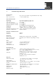
i-Q310 ISO 18000-7 Transponder Series 2 Technical Specifications Performance Read rate Up to 100 tags/s (Collect Tag Identification Code only) Max. response time < 150 ms (single tag) RF Communication Read range Write range Operating frequency Data rate (download to tag) Data rate (upload to reader) Frequency Modulation Sensitivity Maximum transmission power Standard / Certification Up to 100 m (300 feet) @ free air Up to 100 m (300 feet) @ free air 433.92MHz 27.778 Kbits/s 27.778 Kbits/s 433.
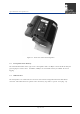
i-Q310 ISO 18000-7 Transponder Series 3 3.1 Transponder Description Housing The SET and CST i-Q310 transponders are made of a rugged plastic housing with IP 65 rating. On the front side (see Fig. 3.1 and 3.2) there are identification labels, which provide information about the type of the tag, the tag manufacturer and prime contractor, certifications, barcode and the IAW MIL-Std-129P markings where appropriate.
i-Q310 ISO 18000-7 Transponder Series Figure 3.2 Front view of the CST transponder 3.2 Transponder Data Memory The CST and SET models of the i-Q310 series transponders offer 128 kBytes of non-volatile memory for general purpose and user data. In addition, 32kBytes of non-volatile memory is available for sensor logging. 3.3 USB Interface The transponders are enabled for fast and secure data transfer using USB connection with mini-B connector.
i-Q310 ISO 18000-7 Transponder Series Figure 3.3 USB connector 3.4 Battery installation and power up indication The transponder ships with the battery reversed; please see Chapter 5 for details on how to power and activate the transponder.
i-Q310 ISO 18000-7 Transponder Series 4 4.1 Installation SET Mounting Options The transponders are designed with two mounting holes so they can be firmly mounted onto virtually any surface. The transponder can be mounted using various methods dependent on the particular application. Among the common types of mounting are: • Screws • Rivets • Double sided tape • Wire ties • Mounting bracket (Fig. 4.1 and 4.2) • Magnetic mount (Fig. 4.3) Figure 4.1 The SET mounting bracket Figure 4.
i-Q310 ISO 18000-7 Transponder Series Figure 4.3 Magnetic mount installation for the SET 4.2 Mounting the SET Transponder The transponder has slots that allow mounting using wire ties without the mounting bracket. The mounting bracket has also openings in order to be wire tied to a post or other object (Fig 2.4). Figure 4.
i-Q310 ISO 18000-7 Transponder Series 4.3 Mounting the CST transponder The CST is intended for ISO shipping containers like the one shown below in Fig 4.5. Figure 4.5 ISO container (typical) The CST transponder is shown below mounted in various orientations. The ISO door mount opening on the CST is 55mm (2.17”) shown in Figure 4.6. It must be mounted on the left door with the antenna outside the container and the sensor body and switch mounted inside the container, shown in Figs 4.8 and 4.9.
i-Q310 ISO 18000-7 Transponder Series Figure 4.7 CST inside left door mounting Figure 4.8 CST inside left door mounting 4.4 Transponder enclosure protection The CST and SET transponders all have enclosures rated at IP 65. This means that the transponders are dust tight and water tight. However care should be taken to not immerse in liquids or subject to powerful jets of water.
i-Q310 ISO 18000-7 Transponder Series 5 5.1 Initial Operation Activating the Transponder The i-Q310 ISO 18000-7 transponders needs to be activated. They are shipped with a reversed battery to prevent communication and battery consumption (Fig. 5.1). Figure 5.1 Battery shown reversed with the negative (-) terminal shown. 5.1.1 How to Activate the Transponder Before use, the battery cover has to be opened, battery flipped over and securely closed. This activates the transponder for operation.
i-Q310 ISO 18000-7 Transponder Series 5.1.2 Battery Replacement Procedure Before starting battery replacement regard following instructions: 1. Due to UL safety clauses this battery must be replaced only by skilled personnel. 2. Warning Fire, explosion and burn hazard Risk of explosion if battery is replaced by an incorrect type Do not recharge, short circuit, crush, disassemble, heat above 100°(212°F) Do not incinerate, or expose contents to water 3. Use only A size 3.
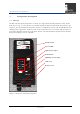
i-Q310 ISO 18000-7 Transponder Series 5.1.3 CST/SET LED description and operation Light Sensor Push Button Humidity Sensor Figure 5.4 LED indicators and sensor inputs 5.1.3.1 Sensor LEDs The sensor LEDs are illuminated when……….??? 5.1.3.2 Light Sensor input Need description for content 5.1.3.3 Push Button Need description for content 5.1.3.
i-Q310 ISO 18000-7 Transponder Series 5.1.3.5 BAT power LED The SET and CST transponders have an LED for battery status as indicated in Fig 5.4. If the battery has more than a 15% charge remaining the LED will be green. Below this level the battery warning flag is set in memory, and the LED will illuminate red. The battery LED will be off when the battery charge is depleted or not installed. 5.2 Configuration The i-Q310 series transponders are not configured directly.
i-Q310 ISO 18000-7 Transponder Series 6 USB Operation Important Note While a transponder is connected via USB to a PC it is continuously powered by the internal battery. In order to save battery life, please close the USB connection and remove the transponder from the USB connection after data transfer. On account of high operating temperature only use usb cable specified up to +80°C (+176°F). 6.1 Using the USB Connection Please see the FDU Software Manual for details. 6.
i-Q310 ISO 18000-7 Transponder Series 7 7.1 Maintenance and Troubleshooting Troubleshooting The transponder does not respond to interrogation at all. • Make sure the battery is inserted in a correct orientation. • Make sure the battery is not depleted. Change the battery. • Tighten the battery cap in order to ensure that both poles are in contact with the transponder’s circuits. The transponder is not accessible through USB.
i-Q310 ISO 18000-7 Transponder Series 7.3 Returns Parts or main components returned for repair or exchange must be handled with great care. All returns should include a completed returns form (see appendix) and be sent to: IDENTEC SOLUTIONS, Inc. 5057 Keller Springs Rd.
i-Q310 ISO 18000-7 Transponder Series 8 Associated Documents Manuals IM.0780.EN IM.0781.EN IM.0782.EN IM.0783.EN System Description, English i-PORT F310 Hardware and Installation Manual, English i-Q310 Series Transponder Installation and Operation Manual for ATN, ATR, DRT and LPT, English i-PORT H310 Handheld Interrogator Module, English Data Sheets ID.0680.EN ID.0681.EN ID.0682.EN ID.0683.EN ID.0684.EN ID.0685.EN ID.0686.EN ID.0689.