
User's Manual


i-PORT F310
Page 11 of 17
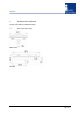
3.3 Power Supply
The i-PORT F310 can be powered parallel in two ways:
• Mains voltage applied to the connector labeled “AC SUPPLY, 47 … 63 Hz, 90 … 260 VAC”
• DC voltage of 10 to 30 VDC applied to the bus connector labeled “RS 485, DC SUPPLY IN, 10 …
30 VDC”.
So it is easy to have the mains supply as standard plus a backup battery for uninterrupted operation
during power failures. Necessary decoupling circuitry is built-in.
Warning
Do not apply supply voltage to the connector labeled “RS 485, DC SUPPLY OUT, 10 … 30 VDC”.
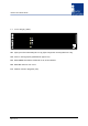
3.4 RS 485 Bus Connectors
Warning
Do not apply supply voltage to the connector labeled “RS 485, DC SUPPLY OUT, 10 … 30 VDC”.
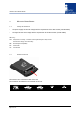
3.5 RS232/USB Connector
This connector is intended for service and set-up during initial operation. In standard operation this
connector is unused. Always use the cap to protect the connector.
Please pay attention to the limitations of cable runs of RS232 (max. 15 m) and USB (max 5 m).
Adapter cables to a PC
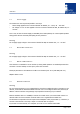
3.6 Ethernet Connector
Warning
Do not connect any device to your network before it has been configured. Before connecting to your
network, check that the desired IP address has been set. A not-configured device may have any IP
address. A device with the wrong settings may impede the functioning of your network.
Ethernet interface with 10 or 100Mbit/s. Connect the central unit to your network with a wired 1:1
network cable. The host connection is a RJ45 socket. Use a regular Ethernet cable here.
The allocation corresponds to that of simple network adapters in PCs (10/100-Base T). Therefore, to
connect to the network or the hub, a simple 1:1 network cable is required.
If you want to connect directly to a computer you must use a so-called crossed cable.