
Reference Manual


113501
9
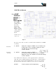
1 2 3 4 5
6 7 8 9
3.1 Opto Coupled Inputs (INPUT 1…4)
The opto-coupled inputs are tied to 5V via the internal opto-isolator, a
limiting resistor and an input status LED. Left open, no current flows
and the status LED is off. If the input is tied to ground, directly through
dry relay contacts, or via a resistor of up to 100 ohms, the LED will
light and the ILR CARD will see the input as ‘pulled low’. Resistance
of greater than 100 ohms may cause the LED to glow but may be
insufficient for the input to be seen as ‘pulled low’.
3.2 Opto Coupled User Outputs (RLY 1a, 1b…4a, 4b)
The four relay outputs are opto-isolated solid state relays offering
5,000V isolation with a current rating of 130mA at 350V. The contacts
are normally open, indicated by the corresponding status LED being
unlit. The status LED lights when the relay contacts ‘close’. Both
contacts are electrically isolated from other system voltages and float.
3.3 Test Serial Port
The test serial port is set to 9600 baud and is a 3 wire port (TX, RX and
GND). It offers 15KV isolation and is true RS232. Data to and from
this port are relayed by the ILR CARD to the host computer.
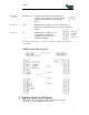
3.3.1
RS232 9 Pin Interface Connection for Test Serial Port
Signal Name Pin
TEST TX 2
TEST RX 3
GND 5
3.4 Bar Code Interface
The Bar Code serial port is set to 9600 baud and is a 4 wire port (TX,
RX, Trigger and GND). It offers 15KV isolation and is true RS232.
Data to and from this port are relayed to the host computer by the ILR
CARD. This connection is intended for a tethered bar code scanner with
the power provided by one of the 5V auxiliary outputs.
This input can be switched from RS232 to RS485 if long
communication range is needed. This connection can be used to connect
any serial input device. The slide switch for RS232 or RS485 is at the
top of the i-PORT, and is described in section
5 Selector Slide Switches
.
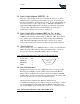
3.4.1
RS232 9 Pin Interface Connection for Bar Code