
Reference Manual


113501
10
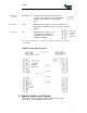
Signal Name Pin
BAR CODE TX 2
BAR CODE RX 3
GND 5
BAR CODE TRIGGER 6
3.4.2
RS485 9 Pin Interface Connection
Signal Name Pin Function
BAR CODE TX 2 Data A
BAR CODE RX 3 Data B
GND 5
BAR CODE TRIGGER 6
3.5 Antenna Multiplexer Outputs
These are the ANT SEL 1 and ANT SEL 2 signals and are intended for
connecting an external antenna multiplexer. The external multiplexer
requires only a single coax cable to run from the MMCX antenna
connection on the ILR-CARD to the multiplexer. In installations where
the i-PORT cannot be installed in close proximity to the antenna
locations the use of an external multiplexer can reduce the coax wiring
requirements.
Note: The total length of coax cabling used to connect an antenna can
affect signal strength from the antenna to the i-PORT. A signal loss
more than 6 dB will reduce read range.
The Antenna Multiplexer Outputs are software controlled digital
outputs, in binary form offering one of four combinations with the two
signals. These are ESD protected, and can drive up to 4mA, within the
voltage range of 0 to 3.3V. They should not be connected to circuits
that may pull the outputs to voltages higher than 3.3V.
4 SMA Coax Connectors (Sockets)
The RF antenna connector on the ILR CARD is a miniature
MMCX connector. This connects to the SMA input connector on
the antenna multiplexer using the 3.5 inch coax pigtail. The
output SMA connectors on the multiplexer connect up to four
antennas to the i-PORT. The ANT 1 to ANT 4 status LEDs
indicate the active antenna. The illuminated LED will change as
the multiplexer sequences through the antennas, with the LED
for the last antenna sequenced remaining illuminated.