IDENTEC SOLUTIONS Model IDS1002 iPOINT X (ATEX) HARDWARE USER MANUAL
iPOINT X – Hardware User Manual | 18.06.2020 Proprietary Notice This document contains confidential information proprietary to IDENTEC SOLUTIONS and may not be used or disclosed to other parties in whole or in part without the prior written authorization from IDENTEC SOLUTIONS.
iPOINT X – Hardware User Manual | 18.06.2020 Radio Frequency Compliance Statement IDENTEC SOLUTIONS is the responsible party for the compliance of the following devices: MODEL: IDS1002 iPOINT X Region/Country Organization Marking EUROPE: EU CE USA: FCC FCC ID OO4-IDS1002 CANADA: IC 3538A-IDS1002 The user(s) of these products are cautioned to only use accessories and peripherals approved, in advance, by IDENTEC SOLUTIONS.
iPOINT X – Hardware User Manual | 18.06.2020 ATEX Certification Equipment or protected system intended for use in potentially explosive atmosphere directive 2014/53/EU.
iPOINT X – Hardware User Manual | 18.06.2020 These notes are not sufficient to guarantee complete protection from electrostatic discharges! We recommend the use of suitable protective equipment. IDENTEC SOLUTIONS does not accept the return of products where the regulations concerning the ESD precautions and protective packaging materials were not followed. Safety Instructions The equipment can be installed in restricted areas.
iPOINT X – Hardware User Manual | 18.06.2020 Contents 1. Preface .................................................................................................................................................................... 7 2. Introduction .............................................................................................................................................................. 8 2.1 iPOINT X and System Description ..................................................................
iPOINT X – Hardware User Manual | 18.06.2020 1. Preface This installation manual must be read carefully prior to starting the installation. The described installation works assuming that installation materials like cables, antennas and any mechanical parts are available. This document is the hardware description of the iPOINT X. This document is intended only for mechanical and electrical installation of these central units.
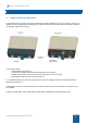
iPOINT X – Hardware User Manual | 18.06.2020 2. Introduction 2.1 iPOINT X and System Description The iPOINT X device provides a functional ATEX/IECEx certified combination of: The “zone location” system of an i-MARK, the long-range Reader functionality of an i-PORT as well as close proximity NFC functionality, encased in an attractive, rugged, IP67 housing. The Housing contains: - 5 Status LEDs (see Section 3.
iPOINT X – Hardware User Manual | 18.06.2020 2.1.1 UHF Interface The UHF interface is a wireless communication interface using the UHF ISM frequency band and IDENTEC’s protocols. The iPOINT X has two internal UHF antennas built in and can communicate up to a range of 500 meters with its Tags. The main benefit of two antennas is the elimination of RF dead spots in static systems. 2.1.2 LF Interface The LF Interface uses IDENTEC’s LFBOOST Marker technology.
iPOINT X – Hardware User Manual | 18.06.2020 2.1.1 LF Limitations for ATEX Due to Barrier (VCL1520) and cable series resistance, it is not possible to operate LF with full power and 12 slots all the time. Therefore, LF operation is limited by firmware according to the slot scheme and the restrictions below.
iPOINT X – Hardware User Manual | 18.06.2020 2.1.2 NFC Interface The NFC Interface is a Near Field Communication interface. The iPOINT X can be used as an entry terminal or for other NFC communication. The range to the Tag is around 10-15cm and is compatible with the i-Q355 Series of Tags as well as standard NFC cards. Copyright © 2020 IDENTEC SOLUTIONS. All rights reserved.
iPOINT X – Hardware User Manual | 18.06.2020 2.2 System Components – Tags Identec offers a wide range of tags that can be used with the iPOINT X. The tags provide long range communication with the readers of up to 500 m (1640 ft), using advanced UHF radio frequency technology. i-Q355 Tags Using advanced UHF radio frequency technology, i-Q355 tags transmit and receive data at distances of up to 250 m (820 feet).
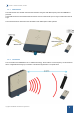
iPOINT X – Hardware User Manual | 18.06.2020 2.3 Ports Overview & Topologies RS422 MASTER RS422 HOST RS422 or RS485 cable connector to the host computer (for connector details see section 2.3.1) This can be used as a communication interface to an access controller (for connector details see section 2.3.1) (RS422 or RS485) ATTENTION: No Daisychaining allowed! Standalone Installation: Copyright © 2020 IDENTEC SOLUTIONS. All rights reserved.
iPOINT X – Hardware User Manual | 18.06.2020 Installation (RS422) with Access control: Installation (RS485) with access control: RS422, RS485 and Power supplies, must go through Barrier VCL1520X outside of the Hazardous Area Please see Barrier „VCL1520X User Manual.pdf “, for more information on the barrier. Copyright © 2020 IDENTEC SOLUTIONS. All rights reserved.
iPOINT X – Hardware User Manual | 18.06.2020 2.3.1 RS422 MASTER Connectors & Pinout Wago: 713-1404 2.3.
iPOINT X – Hardware User Manual | 18.06.2020 2.3.5 Connector coding Important Note: Please check to use the correct coded plug before connecting wires! Both Master and Host connector are the same type, but each one is individually coded so that they cannot be exchanged. The RS 422 Master is coded, according to connector manufacturer recommendation, on pin 1. Nose on pin 1removed on external connector, coding pin added on PCB part.
iPOINT X – Hardware User Manual | 18.06.2020 3. Initial Operation / Configuration The configuration of the iPOINT X is managed via the host software. Available Identec Solutions Software Setup Scout i-Share Crew Companion Please refer to the relevant software User Manuals for details. 3.1 Status LEDs UHF This is the UHF Communication LED. LED blinks green when a valid command has been sent to Tag. It blinks Orange when a response or a broadcast is received. LF This is the LF Communication LED.
iPOINT X – Hardware User Manual | 18.06.2020 4. Mechanical Information & Installation Housing Dimensions 4.1 Opening the connection Chamber 1. 2. 3. 4. Lift up the cover using thumbs from the front side until magnetic connection is released, lift off. Loosen the 8x screws, be aware, DO NOT pull out the screws out completely, the gasket can be damaged. Lift off the lid. Now you have access to the Connection Chamber Note: when replacing the lid, be sure that the sealing gasket is correctly in place.
iPOINT X – Hardware User Manual | 18.06.2020 4.2 Mounting Options The mounting plate can be attached to a wall, pole mount bracket, extension bracket or DIN rail. There are 4 fixing holes for attaching the relevant bracket or screwing to a wall. For mounting with a pole mount bracket or extension bracket, please see relevant Installation guides provided with the kits. For Direct wall mounting, using the mounting plate only, 4x countersunk screws are required with a maximum diameter of 5mm or M5 screws.
iPOINT X – Hardware User Manual | 18.06.2020 Warning: when unmounting device from the mounting plate, first lift the device up, then out; do not pull device directly or there’s a risk of damage. 4.2.1 Optional Extra: Pole Mount Bracket Kit A Pole Mount Bracket Kit is available. - Pole Mount Bracket Kit: o Contains the bracket and accessories o The bracket can be mounted to a wall with M8 Bolts or via threaded rods (e.g.
iPOINT X – Hardware User Manual | 18.06.2020 4.2.2 Optional Extra: Extension Bracket Kit An Extension Bracket Kit is available - Extension Bracket Kit: o Contains the bracket and accessories o The bracket can be mounted to a wall with M8 Bolts or via threaded rods (e.g. wall anchors) o Multiple mounting options, including use of the pole mount bracket o Refer to “Extension Bracket Kit – Quick Installation Guide” documentation for more details. Copyright © 2020 IDENTEC SOLUTIONS. All rights reserved.
iPOINT X – Hardware User Manual | 18.06.2020 Copyright © 2020 IDENTEC SOLUTIONS. All rights reserved.
iPOINT X – Hardware User Manual | 18.06.2020 5. Troubleshooting This chapter covers how faults can be recognized and rectified. There are potentially four main problem sources: The user control system, including task requirements, communication cables, peripheral units with possible object recognition switches. The Crew Companion platform including peripheral units and their cables, also potential object recognition switches.
iPOINT X – Hardware User Manual | 18.06.2020 6.2 Spare Parts Recommended spare parts stock In order to minimize the downtime in the event of a malfunction, it is recommended to have certain spare parts on stock. For larger systems with more than 15 iPOINT Xs, doubling of the recommended stock quantity is recommended. Furthermore, it is advised to have several spare ILR® Tags in stock, corresponding to approx. 0.5 – 1 % of the total number of ILR® Tags.
iPOINT X – Hardware User Manual | 18.06.2020 7.
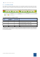
iPOINT X – Hardware User Manual | 18.06.2020 Front View of the Connectors: Ex Electrical Parameters Tamb =-40°C to +70°C Connector Name RS422 MASTER (P1) (Designator) Supply Lines Group Ui (V) IIB Ii (A) IIC P1 - Pin P1.1 P1.2 Value 16,065 P1 - Pin P1.5 P1.7 P1.6 P1.8 1,904 Uo (V) IIB Io (A) IIC Radio PTXMAX (mW) Data Lines 0,474 Pi (W) RS422 MASTER (P1) RS422 HOST (P1) All antennas internal Value 6,135 Frequency UHF 0,196 868 MHz Value 10,0 920 MHz 0,301 P1.6 P1.