
Datasheet

Hazardous location Switches
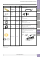
Part Numbers
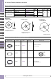
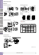
Dimensions
All dimensions in mm
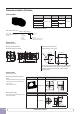
Emergency Stop Switches
Shown with finger-safe contacts
47.4
32.2
38.4
ø 40.0
1.0 to 4.5 (panel thickness)
35.0 67.7
Mounting Hole Dimensions
Panel thickness: 1.0 to 4.5 mm.
33
+0.5
0
4.8
+0.2
0
ø30.5
+0.5
0
50 minimum (*note)
70 minimum
*Note: The meter can be mounted on the top mounting holes
of a standard 50mm mounting centers. The meter can be
mounted on any mounting hole with a 70mm or larger
mounting center.
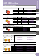
Part Number Operator
Contact
Arrangement
Weight
(Approx.)
Button Color
EU2B-YBV301
•R
ø40 Mushroom
1NC 96g
R : Red
EU2B-YBV311
•R
1NO-1NC
120g
EU2B-YBV302
•R
2NC
EU2B-YBV312
•R
1NO-2NC
144g
EU2B-YBV303
•R
3NC
Specify a terminal style in place of • in the part number: F (Finger-safe terminal),
C (Exposed screw terminal)
Contact arrangement
01:1NC
11:1NO-1NC
02:2NC
03:3NC
12:1NO-2NC
Button color
R:Red
Terminals
F : Finger-safe terminal (IP20)
C:Exposed screw terminal
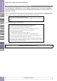
Part Number Structure
EU2B - YBV3 11 F R
Operator (style / function)
BV3:40mm mushroom/push, pull or
twist release
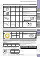
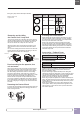
Accessories
Mounting Hole Plug
Used to plug unused mounting holes (ø30.5)
on the mounting panel.
All dimensions in mm
Coating: yellow
Material: Stainless Steel
Appearance Part Number Dimensions
EU9Z-PCE
55.4
50
46
32.2
8
Base
Emergency Stop Switch Padlock
Cover
Used with EU2B-YBV emergency stop switch
to maintain the switch in the latched status.
Appearance Part Number Dimensions / Usage
EU9Z-BP
ø40
1.0 to 10.5
(panel thickness)
13.3
23.2
www.apem-idec.eu
D-066