
Datasheet


Dimensions
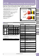
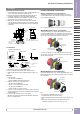
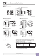
ø29mm Pushlock Turn Reset
HW1B-V3
LOCK
ø29
32
29.4
41.4
25
13
26.5
Terminal Screw M3.5
Panel Thickness 0.8 to 6
Locking Ring
Safety Lever Lock
Gasket
49.4
(
1 or 2 blocks
)
69.4
(
4 blocks
)
1 contact block 2 contact blocks
4 contact blocks
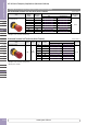
ø40mm Pushlock Turn Reset
HW1B-V4
LOCK
29.4
41.4
32
ø40
13
Safety Lever Lock
25
26.5
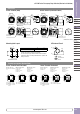
ø60mm Pushlock Turn Reset
HW1B-V5
34.5
15
ø60
Safety Lever Lock
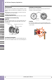
ø40mm Pushlock Key Reset
HW1B-X4
LOCK
29.4
41.4
32
ø40
13
49.4
Safety Lever Lock
25
26.5
ø40mm Push-Pull
HW1B-Y2
LOCK
29.4
41.4
32
ø40
13
Safety Lever Lock
25
26.5
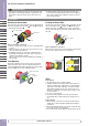
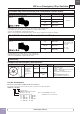
R0.8 max.
0
+0.4
+0.4
0
+0.2
0
ø22.3
3.2
24.1
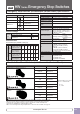
The minimum mounting centers shown below are applicable to emergency stop
switches with one layer of contact blocks (two contact blocks). When two layers
of contact blocks are mounted, determine the minimum mounting centers in
consideration of convenience for wiring.
Minimum Mounting Centers for Emergency Stop Switches
Unit Vertical Spacing Horizontal Spacing
HW1B-V3
HW1B-V4
HW1B-X4
HW1B-Y2
50 mm minimum 50 mm minimum
HW1B-V5 60 mm minimum 60 mm minimum
Note:
When using the safety lever lock, determine the vertical spacing in
consideration of convenience for installing and removing the safety lever lock.
Recommended vertical spacing: 100 mm
Panel Cut-Out
All dimensions in mm.
All dimensions in mm.
ø22
HW Series Emergency Stop Switches
www.apem-idec.eu
D-040