
Datasheet

www.apem-idec.eu
D-025
APEM
Switches &
Pilot Lights
Control Boxes
Emergency
Stop Switches
Enabling
Switches
Safety Products
Explosion Proof
Terminal Blocks
Relays & Sockets
Circuit
Protectors
Power Supplies
LED Illumination
Controllers
Operator
Interfaces
Sensors
AUTO-ID
Emergency Stop Switches
X6
XA
XW
XN
SEMI
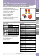
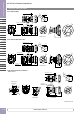
ø16 XA Series Emergency Stop Switches
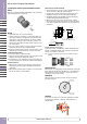
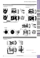
Installing the LED Unit (with Removable Contact
Block)
Align the to of the LED unit with the TOP marking on the contact block.
Push the LED unit into the contact block.
Wiring
1. The applicable wire size is 1.25 mm
2
maximum.
2. Solder the terminal at a temperature of 310 to 350°C within 3 sec
-
onds using a soldering iron. Sn-Ag-Cu type is recommended when
using lead-free solder. When solder ing, do not touch the enabling
switch with the soldering iron. Also ensure that no tensile force is
applied to the ter minal. Do not bend the terminal or apply excessive
force to the terminal.
3. Use a non-corrosive rosin flux. To prevent the flux from entering the
switch while soldering, face the terminals downward.
4. Because the terminal spacing is narrow, use protective tubes or heat
shrinkable tubes to avoid burning of wire coating or short circuit.
Solder/Tab Terminal #110
1. Use #110 receptacles for 0.5mm-thick tabs.
2. Because the terminal spacing is narrow, use protective tubes or heat
shrinkable tubes of 0.5mm minimum in thickness.
3. Do not apply force on the terminals in the direction other than verti
-
cal to the mounting panel, otherwise the terminals will be damaged.
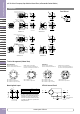
PC Board Terminal
1. When mounting a contact block on a PC board, provide sufficient
rotating space for the PC board when installing and removing the
contact block.
2. When mounting an XA emergency stop switch on a PC board, make
sure that the operator is securely installed.
TOP side
About PC Board and Circuit Design
1. Use PC boards made of glass epoxy copper-clad lami nated sheets of
1.6 mm in thickness, with double-sided through hole.
2. PC boards and circuits must withstand rated voltage and current,
including the instantaneous current and voltage at switching.
3. The minimum applicable load is 5V AC/DC, 1 mA. This value may vary
according to the operating environment and load.
4. Within the 2.8∗ mm areas shown in the figure below, ter minals
touch the PC board, resulting in possible short cir cuit on the printed
circuit. When designing a PC board pattern, take this possibility into
consideration.
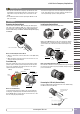
Installing Insulation Terminal Cover
To install the terminal cover (XA9Z-VL2), align the TOP marking on the
terminal cover with TOP marking on the con tact block, and press the
terminal cover toward the contact block.
Note: For wiring, insert the wires into the holes in the terminal cover before
soldering.
Contact Bounce
When the button is reset by pulling or turning, the NC main contacts will
bounce. When pressing the button, the NO monitor contacts will bounce.
When designing a control circuit, take the contact bounce time into
consideration (reference value: 20 ms).
Nameplate
When anti-rotation is not required, remove the projection from the
nameplate using pliers.
Handling
Do not expose the switch to excessive shock and vibration, otherwise
the switch may be deformed or damaged, causing malfunction or
operation failure.
19.8
8.7
19.8
(0.5)
1.6 (PC Board)
(0.5)
(0.5)
2.8
2.8
(0.5)
10-ø1.2 holes
Solder Surface
Surface for installing
components
2.8 2.8
Solder Surface
Surface for installing
components
8.7
Projection
Nameplate