
Datasheet

www.apem-idec.eu
D-011
APEM
Switches &
Pilot Lights
Control Boxes
Emergency
Stop Switches
Enabling
Switches
Safety Products
Explosion Proof
Terminal Blocks
Relays & Sockets
Circuit
Protectors
Power Supplies
LED Illumination
Controllers
Operator
Interfaces
Sensors
AUTO-ID
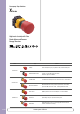
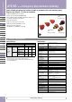
Emergency Stop Switches
X6
XA
XW
XN
SEMI
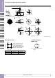
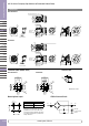
ø16 X6 Series Emergency Stop Switches (Unibody)
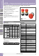
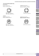
Mounting Hole Layout
The values shown on the left are the
minimum dimensions for mounting
with other ø16 mm pushbuttons. For
other control units of different sizes and
styles, determine the values according to
dimensions, operation, and wiring.
X Y
ø30 mm Button 40 mm min. 40mm min.
ø40 mm Button 50 mm min. 50mm min.
• See D-047 for accessories and replacement parts.
ø16.2
+0.2
0
X
Y
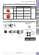
Terminal Arrangement
(Bottom View)
1NC: Terminals located near the TOP
marking
1
TOP
2
1
2
All dimensions in mm.
Dimensions
ø40.0
Unmarked
Arrow Marked
Unmarked
Arrow Marked
ø30mm Button
ø40mm Button
ø40.0
3.6
Solder terminal
(Depth behind the panel: 19.5 mm)
Mounting Hole Layout
17.9
1.7
+0.2
0
0.59.2
Panel thickness 0.8 to 4.5
15.9
+0.2
0
20.6
20.6
ø15.8
ø16.2
+0.2
0
ø30.0
ø30.0
8.0
Solder/tab terminal #110
(Depth behind the panel: 23.9 mm)
Anti-rotation projection
0.59.2