
Datasheet

For more information, visit http://apac.idec.com
B-299
APEM
Switches &
Pilot Lights
Control Boxes
Emergency
Stop Switches
Enabling
Switches
Safety Products
Explosion Proof
Terminal Blocks
Relays & Sockets
Circuit
Protectors
Power Supplies
LED Illumination
Controllers
Operator
Interfaces
Sensors
AUTO-ID
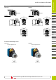
Switches & Pilot Lights
Flush Silhouette
ø16
ø22
ø30
Miniature
Pilot Lights
HW
TW
YW
ø22 YW Series Switches & Pilot Lights
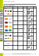
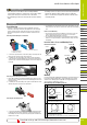
Replacement (LED and incandescent lamps)
Lamps can be replaced using the lamp holder tool (OR-55) from the front of the
panel, or by removing the contact block from the operator unit.
Removing the Lamp from the Front of the Panel
To remove, gently insert the lamp holder tool onto the lamp head. Then push
slightly, and turn the lamp holder tool to the left.
Installing the Lamp from the Front of the Panel
1. To install, insert the lamp head into the lamp holder tool, and hold the lamp
as shown in the figure below.
Lamp Lamp Removal Tool
2. Place the pins on the lamp base to the grooves in the lamp socket. Insert the
lamp and turn it to the right.
Pilot Light Illuminated Pushbutton
Note: LED lamps in unibody pilot lights cannot be replaced.
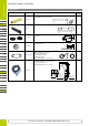
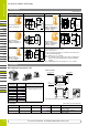
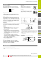
Removing Contact Blocks and Full Voltage Adapters
Insert a flat screwdriver between the latch and contact block mounting adapter,
and disengage the latch.
Make sure to remove the lamp and contact blocks before removing the full
voltage adapter.
Tightening Torque for Terminal Screws
Tighten terminal screws to a torque of 1.0 N·m.
Anti-rotation Ring and Mounting Panel
Turn the TOP marking on the operator and the ▲ mark on the anti-rotation ring
to the recess on the mounting panel.
Projections (p mark)
Anti-rotation Ring
Locking Ring
Panel Thickness 1.2 to 4.5 mm
Mounting Panel Thickness
The mounting panel must be 0.8 to 6.0 mm in thickness. When optional
accessories are added, the applicable panel thickness changes as shown below.
P
anel Thickness
0.8 to 6 mm
Panel Thickness
0.8 to 3.2 mm
Padlock Cover
HW9Z-KL1P
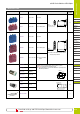
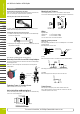
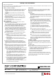
Wiring
Applicable Wires
Stranded wire: 2.0 mm
2
maximum (14AWG)
Solid wire: ø1.6 mm maximum (16AWG)
One or two wires can be connected to the terminal.
Applicable Crimping Terminals
[Spade terminal]
When using crimping terminals, be sure to use insulating tubes or use insulated
crimping terminals.
Note: Ring terminals cannot be used.
11.5 max.
8.1 max.
6.9 max.
3.6 min.
0.5 min.
Crimping Termina
l
Wire
Insulation Tube
[Ferrule]
When connecting two ferrules to one terminal, use ferrules without insulation.
8.0 max.
1.7 max.
Insulation
8.0 max.
1.7 max.
When using spade terminals or ferrules, insert them to the bottom.
[Solid Wire]
When connecting two wires directly, use wires of the same size.
8.0 max.
ø1.6 max.
Contact Bounce
When pressing or turning the operator, the NC and NO contacts will
bounce. When designing a control circuit, take the contact bounce time into
consideration (reference value: 20 ms).
Lamp
1
3
22
Full Voltage Adapter
Contact Block
Instructions
For more information, visit https://www.idec-emea.com