
Datasheet

Download catalogs and CAD from http://apac.idec.com
B-298
APEM
Switches &
Pilot Lights
Control Boxes
Emergency
Stop Switches
Enabling
Switches
Safety Products
Explosion Proof
Terminal Blocks
Relays & Sockets
Circuit
Protectors
Power Supplies
LED Illumination
Controllers
Operator
Interfaces
Sensors
AUTO-ID
Switches & Pilot Lights
Flush Silhouette
ø16
ø22
ø30
Miniature
Pilot Lights
HW
TW
YW
ø22 YW Series Switches & Pilot Lights
• Turn off the power to the YW series before starting installation,
removal, wiring, maintenance, and inspection of the products. Failure
to turn power off may cause electrical shocks or re hazard.
• To avoid burning your hand, use the lamp holder tool when replacing
lamps.
• For wiring, use wires of a proper size to meet the voltage and current
requirements. Tighten the M3.5 terminal screws to a tightening
torque of 1.0 N·m. Failure to tighten the terminal screws may cause
overheating and re.
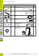
Panel Mounting
• Remove the contact block from the operator (for pilot lights, remove the
transformer or full voltage unit from the pilot light). Remove the locking ring
from the operator. Insert the operator into the panel cut-out from the front,
tighten the locking ring from the back, then install the contact block to the
operator.
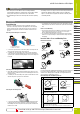
Removing and Installing the Contact Block
➀ Pull up the locking lever.
➁ Turn the lever to the left.
➂ Pull out the contact bloc
k
1. To remove the operator from the contact block, pull up the locking lever and
turn it to the left. Then the operator can be pulled out.
2. To reinstall, place the TOP marking on the operator and the TOP marking
on the contact block mounting adapter in the same direction, and insert the
operator into the contact block mounting adapter. Then turn the locking lever
to the right.
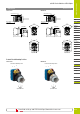
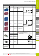
Removing and Installing the Transformer
1. Insert a flat screwdriver (5 mm wide at maximum) into the latch hole on the
transformer unit as shown in the photo below, and disengage the latch. Then
pull out the operator.
2. To reinstall, place the TOP marking on the operator and the latch in the same
direction, and push the operator into the transformer.
➀
➁
Removing the Full Voltage Unit
➁
➀
1. To remove the full voltage unit, squeeze the full voltage unit from both sides
to disengage the latch as shown, and pull it out. Like the transformer unit,
the full voltage unit can also be pulled out by inserting a flat screwdriver into
the latch hole as shown.
2. To reinstall, place the TOP markings on the operator and the latch on the full
voltage unit in the same direction, and insert the operator into the full voltage
unit.
Notes for Panel Mounting
1.
Use the optional locking ring wrench (MW9Z-T1) to mount the operator onto
a panel. Tightening torque must not exceed 2.0 N·m. Do not use pliers.
Excessive tightening will damage the locking ring.
2. For contact blocks and transformers housing LED and incandescent lamps,
make sure not to press the lamps too hard, otherwise the lamp socket may
be damaged.
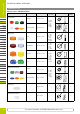
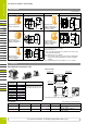
Insertion Order of Lens and Marking Plate
Illuminated Pushbutton Pilot Light
Marking
For YW series pilot lights and illuminated pushbuttons, legends and symbols can
be engraved on built-in marking plates, or printed mylar film can be inserted
under the lens for labeling purposes. Mylar film is not supplied with the YW
series and must be supplied by the end user.
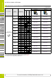
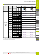
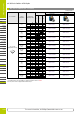
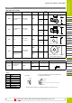
Built-in Marking Plate and Marking Film Size
Unit Pilot Light Illuminated Pushbutton
Built-in Marking Plate
Engraving depth: 0.5 mm maximum
Marking plate material: White acrylic
Applicable Marking Film
0.1-mm-thick × 2 sheets or 0.2-mm-thick × 1 sheet
Film material: Mylar (recommended)
Note: Marking lm is not supplied with the pilot light or illuminated pushbutton.
Marking Plate
Lens
Extended
Marking Plate
Lens
Mushroom
With Full Shroud
Marking Plate
Lens
Full Shroud
Flush
Extended
Dome
Flush Marking
Marking Plate
Lens
Lens
ø21.0
1.0
Engraving Area
ø15.2
1.2
Engraving Area
ø22.7
20.8
-0.2
0
-0.2
0
-0.2
0
ø17.2
-0.2
0
15.0
Safety Precautions
Instructions
Download catalogs and CAD from https://www.idec-emea.com