
Datasheet


7
Instructions
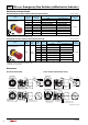
XW Series Emergency Stop Switches (w/Mechanical Indicator)
ø22
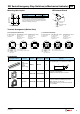
IP20 Protection Terminal Cover
XW9Z-VL2MF
ToinstalltheIP20protectioncover,aligntheTOPmarkingonthe
coverwiththeTOPmarkingonthecontactblock,andpressthe
covertowardthecontactblock.
TOP marking
TOP marking
(Press)
Notes:
1. Onceinstalled,theXW9Z-VL2MFcannotberemoved.
2.TheXW9Z-VL2MFcannotbeinstalledafterwiring.
3.WiththeXW9Z-VL2MFinstalled,crimpingterminalscannotbe
used.Usesolidwires.
4.MakesurethattheXW9Z-VL2MFissecurelyinstalled.IP20
cannotbeachievedwheninstalledloosely,andelectricshocks
mayoccur.
Contact Bounce
Whenthebuttonisresetbypullingorturning,theNCmaincontacts
willbounce.Whenpressingthebutton,theNOmonitorcontactswill
bounce.
Whendesigningacontrolcircuit,takethecontactbouncetimeinto
consideration(referencevalue:20ms).
LED Illuminated Switches
AnLEDlampisbuiltintothecontactblockandcannotbereplaced.
Nameplate
Whenanti-rotationisnotrequired,removetheprojectionfromthe
nameplateorswitchguardusingpliers.
Projection
Nameplate
Handling
Donotexposetheswitchtoexcessiveshocksandvibrations,
otherwisetheswitchmaybedeformedordamaged,causing
malfunctionoroperationfailure.
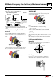
Wiring
1.Wirethickness:0.75to1.25mm
2
(AWG18to16)
Applicable Crimping Terminals Solid Wire
Wire
Insulating Tube
Crimping Terminal
4.7 to 5.9
6.0 max.
3.2 min.
4.7 to 5.9
3.0 max.
ø3.2 min.
Wire
Insulating Tube
Crimping
Terminal
4.7 to 5.9
ø6.0 max.
4.7 min.
6.2 max.
ø1.2 max.
• Only solid wires can
be used on the IP20
ngersafe terminal
type.
Ring Terminal Spade Terminal
•Besuretoinstallaninsulatingtubeonthecrimpingterminal.
2.TightentheM3terminalscrewtoatighteningtorqueof0.6to1.0
N·m.
Installing & Removing Terminal Covers
XW9Z-VL2M
Toinstalltheterminalcover,aligntheTOPmarkingontheterminal
coverwiththeTOPmarkingonthecontactblock.Placethetwo
projectionsonthebottomsideofthecontactblockintotheslots
intheterminalcover.Presstheterminalcovertowardthecontact
block.
TOP marking
Place the projections
onto the contact block.
Press the
terminal cover
Toremovetheterminalcover,pulloutthetwolatchesonthetop
sideoftheterminalcover.Donotexertexcessiveforcetothe
latches,otherwisethelatchesmaybreak.
TOP markings
Pull out the latches.
(13/04/04)