
Datasheet

Instructions
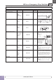
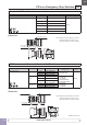
Tightening Torque for Terminal Screws
Tighten terminal screws to a torque between 1.0 and 1.3 N·m.
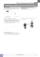
Anti-rotation Ring and Mounting Panel
Turn the TOP marking on the operator and the
mark on the anti-
rotation ring to the recess on the mounting panel.
Projections (▲ mark)
Anti-rotation Ring Locking Ring
Panel Thickness 1.2 to 4.5 mm
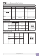
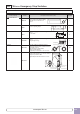
Mounting Panel Thickness
The mounting panel must be 0.8 to 6.0 mm in thickness. When
optional accessories are added, the applicable panel thickness
changes as shown below.
Panel Thickness
0.8 to 6 mm
Nameplate
Panel Thickness
0.8 to 3.2 mm
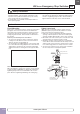
Contact Bounce
When the button is reset by pulling or turning, the NC main contacts
will bounce. When pressing the button, the NO monitor contacts will
bounce.
When designing a control circuit, take the contact bounce time into
consideration (reference value: 20 ms).
Nameplate
When anti-rotation is not required, remove the
projection from the nameplate using pli ers.
Handling
Do not expose the switch to excessive shock
and vibration, otherwise the switch may be
deformed or damaged, causing malfunction or
operation failure.
LED Illumination
LED lamps consist of semiconductors. If the
applied voltage exceeds the rated voltage,
LED elements deteriorate due to overheat, resulting in significant
decrease in luminance, hue change, or failure of lighting. Also, if
extraneous noise, transient volt age, or transient current is applied
to the circuit, similar effects will be caused. When using LED lamps,
observe the following instructions.
Rated Voltage
The LED illuminated units are rated at 6V, 12V, 24V, 110V, or
230/240V AC/DC, and can be used within ±10% the rated voltage of
either AC or DC, except the 230/240V AC/DC can be used on 250V
AC/DC maximum.
DC Power
1. Switching power supply
Regulated voltage from switching power supply is best suited.
Make sure to use within the rated voltage of the LED lamp.
2. Rechargeable battery
Note that the battery voltage may exceed the rated voltage of the
LED lamp while the battery is being charged and immediately
after the charging is complete. Be sure to use the LED lamp on a
voltage of ±10% the rated voltage, except the 230/240V AC/DC
on 250V AC/DC maximum.
3. Full-wave rectification
Since the LED lamp is AC/DC compatible, a diode bridge for recti-
fication is not necessary. If the LED lamp is used on a full-wave
rec tification current through a diode bridge, the rectifier diodes will
reduce the voltage, resulting in lower luminance.
4. Single-phase half-wave rectification
This is not suitable for the power source of LED lamps. Use con-
stant-voltage DC power.
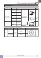
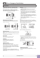
Noise
LED elements deteriorate due to extraneous noise, resulting in
sig nificant decrease in luminance, hue change, or failure of lighting.
When such effects are anticipated, take a protection measure shown
below, such as RC elements or a surge absorber.
[Protection Example 1] For AC circuit
LED with
transformer
LED
R
C
LED
Ry
Relay
coil or
solenoid
R
C
LED with
transformer
(Reference values)
R: 120Ω
C: 0.1 µF
[Protection Example 2] For DC circuit
Ry
LED
Diode
Relay
coil or
solenoid
+
–
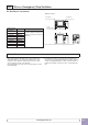
Countermeasures against Dim Lighting
1. Leakage currents through the transistors or a contact protection
circuit may cause the LED lamp to illuminate dimly even when the
output is off.
2. When the LED lamp is illuminated by a transistor output, take the
following measure.
[Circuit Example]
Connect shunt resistor R in parallel with the LED lamp.
R
Io
Io: Leakage current when the output is off
R: Shunt resistor
LED
Ordering Information
• When ordering, specify the Part No. and quantity.
•
Replacement contact blocks are supplied in a package containing
10 pieces.
ø22
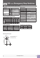
YW Series Emergency Stop Switches
www.apem-idec.eu
D-050