Safety light curtains with infrared beams INSTRUCTION MANUAL
DATASENSOR S.p.A. Via Lavino 265 40050 Monte S. Pietro - Bologna - Italy Tel: +39 051 6765611 Fax: +39 051 6759324 http://www.datasensor.com e-mail: info@datasensor.com DATASENSOR S.p.A. cares for the environment: 100% recycled paper. DATASENSOR S.p.A. reserves the right to make modifications and improvements without prior notification. 826003870 Rev.
We DATASENSOR S.p.A. Via Lavino, 265 40050 Monte San Pietro Bologna - Italy DECLARATION OF CONFORMITY Declare, under the terms of EC Machine Directive 98/37/EEC, Appendix II C, that the product(s) SG4-XX-XXX-OO-X SAFETY LIGHT CURTAINS ELECTRO-SENSITIVE PROTECTIVE EQUIPMENT (TYPE 2) AND ALL ITS MODELS are safety components for a machine constructed as per the EC Directive 98/37/EEC. This declaration will lose its validity if any modification to devices is applied without prior consultation.
SG4-B Series Instruction Manual INDICE 1. GENERAL INFORMATION .......................................................................................... 1 1.1. General Description of the safety light curtains................................................... 1 1.1.1. Package contents ................................................................................... 3 1.2. New features compared to SE4-Plus series (with EDM function) ....................... 3 1.3. How to choose the device ................
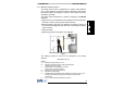
Instruction Manual SG4-B Series 1. GENERAL INFORMATION 1.1. General Description of the safety light curtains The safety light curtains of the SG4 series are optoelectronic multibeam devices that are used to protect working areas that, in presence of machines, robots, and automatic systems in general, can become dangerous for operators that can get in touch, even accidentally, with moving parts.
SG4-B Series Instruction Manual The device consists in 2 units that, according to the model, are composed by one or several emitting and receiving modules. The receiver checks the control operations and safety actions. During installation, an user interface facilitates the alignment of both units (see section 5 “Alignment procedure”).
Instruction Manual SG4-B Series 1.1.1. Package contents Package contains the following objects: Receiver (RX) Emitter (TX) Installation Quick Guide of SG4-B curtain Biannual checklist and periodical maintenance schedule CD with instruction manual and other documents 4 angled fixing brackets and specific fasteners 2 angled fixing brackets for models with heights included between 1200 and 1800 mm 1.2.
SG4-B Series Instruction Manual 1.3. How to choose the device There are at least three different main characteristics that should be considered when choosing a safety light curtain, after having evaluated the risk assessment: 1.3.1. Resolution The resolution of the device is the minimum dimension that an opaque object must have in order to obscure at least one of the beams that constitute the sensitive area. The resolution strictly depends on the part of the body to be protected.
Instruction Manual SG4-B Series 1.3.2. Controlled height The controlled height is the height protected by the safety light curtain (Hp) Fig.
SG4-B Series Instruction Manual 1.3.3. Minimum installation distance The safety device must be positioned at a specific safety distance (Fig. 3). This distance must ensure that the dangerous area cannot be reached before the dangerous motion of the machine has been stopped by the ESPE. The safety distance depends on 4 factors, according to the EN-999 Standard: Response time of the ESPE (the time between the effective beam interruption and the opening of the OSSD contacts).
Instruction Manual SG4-B Series NOTE: K value is: 2000 mm/s if the calculated value of S is ≤ 500 mm 1600 mm/s if the calculated value of S is > 500 mm When devices with > 40 mm resolution are used, the height of the top beam has to be ≥ 900 mm (H2) from machine supporting base while the height of the bottom beam has to be ≤ 300 mm (H1). If the safety light curtain must be mounted in a horizontal position (Fig.
SG4-B Series Instruction Manual Practical examples Let's suppose to have a light curtain with height = 600 mm To calculate the distance of the device from the ESPE, in a vertical position, the following formula is used: S = K*T + C where: T t1 t2 C D = = = = = t1 + t2 ESPE response time + SE-SR2 relay release time (max 80 ms) Machine total stopping time. 8 * (d – 14) for devices with resolution <= 40 mm resolution In all cases, if K = 2000mm/sec then S > 500 mm.
Instruction Manual SG4-B Series Example 1: Operating point protection on drilling machines The operator positions the part and takes it back after machining. The operator must be protected against possible abrasions while working. Solution: SG4-B 14 mm safety light curtain is especially suitable for this kind of application, which requires the installation of the device directly on the machine.
SG4-B Series Instruction Manual Example 3 : Paper cutting machines These machines typically cut paper to a specific size for newspapers or special applications. The operator must be protected against abrasion or cuts by cutter blades. Solution: SG4-B 30 mm safety light curtain is especially suitable for this kind of application, which require the installation of the device directly on the machine.
Instruction Manual SG4-B Series 1.5. Safety information For a correct and safe use of the safety light curtains of the SG4 series, the following points must be observed: The stopping system of the machine must be electrically controlled. This control system must be able to stop the dangerous movement of the machine within the total machine stopping time T as per paragraph 1.3.3, and during all working cycle phases.
SG4-B Series Instruction Manual 2. INSTALLATION MODE 2.1. Precautions to be observed for the choice and installation Make sure that the protection level assured by the SG4 device (Type 4) is compatible with the real danger level of the machine to be controlled, according to EN 954-1 and EN 13849-1. The outputs (OSSD) of the ESPE must be used as machine stopping devices and not as command devices. The machine must have its own START command.
Instruction Manual SG4-B Series 2.2. General information on device positioning The safety light curtain should be carefully positioned, in order to reach a very high protection standard. Access to the dangerous area must only be possible by passing through the protecting safety light beams. Fig.5a shows some examples of possible access to the machine from the top and the bottom sides.
SG4-B Series Instruction Manual When the installation of the safety light curtain near to the dangerous area is not possible, a second light curtain must be mounted in a horizontal position in order to prevent any lateral access, as shown in Fig.6b. If the operator is able to enter the dangerous area, an additional mechanical protection must be mounted to prevent the access. NO Fig. 6a YES Fig. 6b 2.2.1. Minimum installation distance Refer to paragraph1.3.3.
Instruction Manual SG4-B Series 2.2.2. Minimum distance from reflecting surfaces Reflecting surfaces placed near the light beams of the safety device (over, under or laterally) can cause passive reflections. These reflections can affect the recognition of an object inside the controlled area. However, if the RX receiver detects a secondary beam (reflected by the side-reflecting surface) the object might not be detected, even if the object interrupts the main beam. Fig.
SG4-B Series Instruction Manual It is thus important to position the safety light curtain according to the minimum distance from reflecting surfaces. The minimum distance depends on: operating distance between emitter (TX) and receiver (RX); real aperture angle of ESPE (EAA); especially: for ESPE type 4 EAA = 5° (α = ± 2,5°) Diagram of Fig. 8 shows the minimum distance from the reflecting surface (Dsr), based on the operating distance: ESPE Type 4 Fig.
Instruction Manual SG4-B Series 2.2.3. Distance between homologous devices If different safety devices have to be installed in adjacent areas, the emitter of one device must not interfere dangerously with the receiver of the other device. The TXB interfering device must be positioned outside a minimum Ddo distance from the TXA – RXA emitter-receiver couple axis.
SG4-B Series Instruction Manual The following table shows, for convenience, the values of the minimum installation distances relative to some operating distances: Operating distance (m) 3 6 10 19 Minimum installation distance (m) 0,3 0,4 0,5 0,6 WARNING: the interfering device (TXB) must be positioned at the same Ddo distance, calculated as shown above, even if closer to TXA respect to RXA.
Instruction Manual SG4-B Series Installation precautions have to be taken to avoid interference between homologous devices. A typical situation is represented by the installation areas of several adjacent safety devices aligned one next to the other, for example in plants with different machines. Fig.9 provides two examples: NO YES RX TX YES Fig.
SG4-B Series Instruction Manual 2.2.4. Emitter and receiver orientation The two units shall be assembled parallel each other, with the beams arranged at right angles with the emission and receiving surface, and with the connectors orientated towards the same direction. The configurations shown in Fig.10 must be avoided: NO NO Fig. 10 2.2.5.
Instruction Manual SG4-B Series The operator must respect the following precautions when using the deviating mirrors: The alignment of the emitter and the receiver can be a very critical operation when deviating mirrors are used. Even very small displacements of the mirror is enough to lose alignment. The use of Datasensor laser pointer accessory is recommended under these conditions. The minimum safety distance (S) must be respected for each single section of the beams.
SG4-B Series Instruction Manual Fig. 12 ESPE has to be correctly aligned, press slightly on the product side in both directions the red LED must not turn on . The activation of the TEST function causes the opening of the on and controlled machine stop). OSSD outputs (red LED The response time at machine STOP, including the ESPE and machine response times, must be included in the limits defined in the calculation of the safety distance (refer to section 2 “Installation modes”).
Instruction Manual SG4-B Series 3. MECHANICAL MOUNTING The emitting (TX) and receiving (RX) units must be installed with the relevant sensitive surfaces facing each other. The connectors must be positioned on the same side and the distance must be included within the operating range of the model used (see section 10 “Technical data”). The two units must be positioned the most aligned and parallel possible. The next step is the fine alignment, as shown in section 5 “Alignment Procedure”.
SG4-B Series Instruction Manual Rotating brackets Rotating brackets (Fig.14), available upon request, can be used as an alternative or together with angled brackets. For fixing with rotating bracket, refer to Fig.14. Fig. 14 In case of applications with particularly strong vibrations, vibration dampers together with mounting brackets are recommended to reduce the impact of the vibrations. Fig. 15 The recommended mounting positions according to the light curtain length are shown in Fig.
Instruction Manual MODEL L (mm) A (mm) B (mm) C (mm) SG4-xx-015-OO-E 216.3 108 54 - SG4-xx-030-OO-E 366.2 216 75 - SG4-xx-045-OO-E 516.3 316 100 - SG4-xx-060-OO-E 666.2 366 150 - SG4-xx-075-OO-E 816.3 466 175 - SG4-xx-090-OO-E 966.2 566 200 - SG4-xx-105-OO-E 1116.2 666 225 - SG4-xx-120-OO-E 1266.3 966 150 483 SG4-xx-135-OO-E 1416.2 1066 175 533 SG4-xx-150-OO-E 1566.3 1166 200 583 SG4-xx-165-OO-E 1716.3 1266 225 633 SG4-xx-180-OO-E 1866.
SG4-B Series Instruction Manual 4. ELECTRICAL CONNECTIONS All electrical connections to the emitting and receiving units are made through a male M12 connector, located on the lower part of the two units. For receiver a M12 8-pole connector is used, while for emitter a M12 4-pole connector is used. RECEIVER (RX): OSSD1 EDM OSSD2 0V N.O. +24 VDC 6 = = = = = = = = white brown green yellow grey pink blue red = = = = = = = = 4 +24 VDC N.C.
Instruction Manual Function SG4-B Series Connection to Status + 24 VDC TEST ON Not connected or 0V TEST OFF + 24 VDC RESET ON Not connected or 0V RESET OFF Normally closed contact for a forceguided relay EDM is active Not connected or 0V EDM is not active + 24 VDC EDM OFF Not connected or 0V EDM ON OSSD1 AUTOMATIC RESTART OSSD2 MANUAL RESTART TEST RESET EDM EDM SELECTION MAN/AUTO RESTART 27
SG4-B Series Instruction Manual 4.1. Notes on connections For the correct functioning of the SG4 safety light curtains, the following precautions regarding the electrical connections have to be respected: Do not place connection cables in contact with or near high-voltage cables and/or cable undergoing high current variations (e.g. motor power supplies, inverters, etc.
Instruction Manual SG4-B Series Example: connection to the safety relay. Fig. 16 The figures show the connection between the safety light curtains and the safety relay of the SE-SR2 series functioning in the Automatic Restart mode (left side) and Manual Restart with monitoring (right side). Do not use varistors, RC circuits or LEDs in parallel at relay inputs or in series at OSSD outputs.
SG4-B Series Instruction Manual Connect both OSSDs to the activating device. Failure to connect an OSSD to the activating device jeopardises the system safety degree that the light curtain has to control. YES NO Fig. 17 Fig. 18 NO NO Fig. 19 Fig.
Instruction Manual SG4-B Series 4.2. Ground connection SG4 safety light curtain units are preset for easy ground connection. A special compartment, positioned onto caps and marked with the special symbol shown in Figure 21, allows connection with ground cable by means of an additional screw coming with the equipment. Fig. 21 Ground connection configuration is the most common and guarantees the best immunity against electromagnetic disturbances. SG4-B can function even without ground connection.
SG4-B Series Instruction Manual The ground connection of the two units is not necessary for Class III, while the use of a duly-insulated low-voltage feeder type SELV or PELV is compulsory. In this case, we recommend covering the earth symbol present on the caps of the two units with a blank sticker. The ground connection of the two units is compulsory for Class I, while the use of a duly-insulated feeder type SELV or PELV is not compulsory but anyway recommended.
Instruction Manual SG4-B Series 5. ALIGNMENT PROCEDURE The alignment between the emitting and the receiving units is necessary to obtain the correct functioning of the light curtain. A good alignment prevents outputs instability caused by dust or vibrations. The alignment is perfect if the optical axes of the first and the last emitting unit's beams coincide with the optical axes of the corresponding elements of the receiving unit.
SG4-B Series Instruction Manual The standard installation described hereinafter is the one shown in Fig. 22, i.e. with the bar assembled with the connectors pointing down. 5.1. Correct alignment procedure The light curtain alignment can be effected only after having completed the mechanical installation and the electrical connections as described above. Compare alignment results with those given in the following table. NOTE: To enter alignment mode connect the device as described in section 6.
Instruction Manual SG4-B Series A Keep the receiver in a steady position and set the emitter until the yellow LED ( SYNC) is OFF. This condition shows the alignment of the first synchronisation beam. B Rotate the emitter, pivoting on the lower optics axis, until the yellow LED ( LAST) is OFF. NOTE: Ensure that the green LED ( ON.
SG4-B Series Instruction Manual 6. FUNCTIONING MODE 6.1. Restart mode The interruption of a beam due to an opaque object causes the opening of OSSD outputs and the stop of the safety light curtain, SAFE (BREAK) condition . ESPE standard operation can be reset (OSSD safety contact closing = NORMAL OP. condition, ) in two different ways: Automatic Restart, After activation, ESPE resets to standard operating condition once the object has been removed from the controlled area.
Instruction Manual SG4-B Series Select either automatic or manual restart by connecting pin of RX connector (see section 4 "Electrical connections") 6.2. Test function The TEST function can be activated by keeping a normally open external contact (TEST push-button), closed for at least 0.5 seconds. The TEST signal is active high. 6.3. Reset function The RX light curtain has a RESET function which is activated after an internal error.
SG4-B Series Instruction Manual 6.4. EDM function The light curtain has a function for monitoring actuation external devices (EDM). This function can be enabled or deactivated. EDM enabled: - Disconnect or connect to the ground pin 3 of receiver M12 8-pole connector (EDM enabling = ON). - Connect EDM input (pin 4 of M12 8-pole – RX) to a 24 VDC normally closed contacts of the device to be monitored. NOTE: The decimal dot on the display shows that the function is enabled.
Instruction Manual SG4-B Series 6.5. Alignment aid function SG4-B light curtain is fitted with a system which informs the user about reached alignment degree. The alignment function can be selected on device starting by keeping closed RESET/RESTART N.O. contact for at least 0.5 seconds (Fig.24). Alignment mode timing LIGHT CURTAIN STATOSTATUS DELLA BARRIERA ON OFF RESET 24Vdc 0Vdc 0.5 s LIGHT CURTAIN ( ALIGNMENT STATO DELLA STATUS BARRIERA ( ALLINEAMENTO ) ON OFF Fig.
SG4-B Series Instruction Manual 7. DIAGNOSTIC FUNCTIONS 7.1. User interface Curtain operating status is visualised through an one-digit display present on both the receiver and emitter units. SG4-B also has four LEDs on the receiver and two LEDs on the emitter. Fig.25 shows all LEDs signalling modes: OFF, ON and BLINKING. LED OFF LED BLINKING LED ON Fig.
Instruction Manual SG4-B Series 7.2. Dagnostic messages The operator can evaluate the main causes of the system stop or failure through the display and signalling LEDs. For Receiver: Function Normal operation 41 Status Meaning Alignment See section 5 TEST (red ON) Light curtain being tested.
SG4-B Series Function Instruction Manual Type OSSD error (red ON) Internal error (red ON) Error status Optical error (red ON) EDM error (red ON) Restart selection error (red ON) No power supply (LEDs OFF) Check and repair LED DIGIT Check OSSD connections. Make sure that they are not in contact with one another or with the supply cables, then Reset. If the failure continues contact DATASENSOR Switch OFF and switch ON the power supply circuit. If the failure continues contact DATASENSOR Reset.
Instruction Manual SG4-B Series For Emitter: Function Normal operation Function Error status 43 Status Meaning TEST (green ON) Light curtain being tested. OSSD status on the receiver must be OFF Emission (green ON yellow ON) Light curtain in normal operating condition Type Check and repair Internal error (green ON) Switch OFF and switch ON the power supply circuit. If the failure continues contact DATASENSOR Optical error (green ON) Switch OFF and switch ON the power supply circuit.
SG4-B Series Instruction Manual 8. PERIODICAL CHECKS The following is a list of recommended check and maintenance operations that should be periodically carried-out by qualified personnel (Paragraph 2.2.6 “Controls after first installation”) Check that: ) during beam interruption along the The ESPE stays locked ( entire protected area, using the suitable “Test Piece” (*) The ESPE is correctly aligned. Press slightly product side, in both ) must not turn ON.
Instruction Manual SG4-B Series 8.1. General informatio and useful data Safety MUST be a part of our conscience. The safety devices fulfil their safety function only if they are correctly installed, in accordance with the Standards in force. If you are not certain to have the expertise necessary to install the device in the correct way, DATASENSOR Technical Support is at your disposal to carry out the installation. The device uses fuses that are not self-resetting.
SG4-B Series Instruction Manual 8.2. Warranty DATASENSOR S.p.A. guarantees each brand new SG4 system, under standard use conditions, against manufacturing defects in material and workmanship for a period of 36 (thirty-six) months from the date of manufacturing. DATASENSOR S.p.A. will not be liable for any damages to persons and things caused by failure to stick to the correct installation modes and device use. Warranty validity is subject to the following conditions: User shall notify DATASENSOR S.p.A.
Instruction Manual SG4-B Series 9. DEVICE MAINTENANCE SG4-B safety light curtains do not require special maintenance operations. To avoid the reduction of the operating distance, optic protective front surfaces must be cleaned at regular intervals. Use soft cotton cloths damped in water. Do not apply too much pressure on the surface in order to avoid making it opaque.
SG4-B Series Instruction Manual 10. TECHNICAL DATA ELECTRICAL DATA Power supply (Vdd): Consumption (TX): Consumption (RX): Outputs: Short-circuit protection: Output current: Output voltage – status ON: Output voltage – status OFF: Capacitive load Response times: Controlled height: Safety category: Auxiliary functions: Electrical protection: Connections: Cable length (for power supply): OPTICAL DATA Light emission ( ): Resolution: Operating distance: 24 Vdc ± 20% 2.5 W max 3.
Instruction Manual SG4-B Series 11. LIST OF AVAILABLE MODELS Controlled height (mm) No.
SG4-B Series Instruction Manual 12. OVERALL DIMENSIONS MODEL SG4-xx-015-OO-E SG4-xx-030-OO-E SG4-xx-045-OO-E SG4-xx-060-OO-E SG4-xx-075-OO-E SG4-xx-090-OO-E SG4-xx-105-OO-E SG4-xx-120-OO-E SG4-xx-135-OO-E SG4-xx-150-OO-E SG4-xx-165-OO-E SG4-xx-180-OO-E xx = L1 233.3 383.2 533.2 683.2 833.2 983.2 1133.2 1283.3 1433.2 1583.3 1733.3 1883.3 L2 153.3 303.2 453.3 603.2 753.3 903.2 1053.2 1203.3 1353.2 1503.3 1653.3 1803.
Instruction Manual 13.
SG4-B Series Instruction Manual 13.
Instruction Manual 14.
SG4-B Series Instruction Manual Deviating mirrors MODEL DESCRIPTION L1 (mm) L2 (mm) SE-DM 500 Deviating mirror H = 550 mm 554 384 SE-DM 600 Deviating mirror H = 700 mm 704 534 SE-DM 800 Deviating mirror H = 900 mm 904 734 SE-DM 900 Deviating mirror H = 1000 mm 1004 834 SE-DM 1200 Deviating mirror H = 1270 mm 1264 1094 SE-DM 1500 Deviating mirror H = 1600 mm 1604 1434 54
Instruction Manual SG4-B Series Column and floor stands L (mm) X (mm) SE-S 800 Column and floor stand H= 800 mm 800 30x30 SE-S 1000 Column and floor stand H= 1000 mm 1000 30x30 SE-S 1200 Column and floor stand H= 1200 mm 1200 30x30 SE-S 1500 Column and floor stand H= 1500 mm 1500 45x45 SE-S 1800 Column and floor stand H= 1800 mm 1800 45x45 MODEL 55 DESCRIPTION
SG4-B Series Instruction Manual 86 Protective stands sp.2 sm.50x45° N°4 100 Ø6.
Instruction Manual SG4-B Series Connection cables 57 MODEL CS-A1-02-U-03 CS-A1-02-U-05 CS-A1-02-U-10 CS-A1-02-U-15 CS-A1-02-U-25 DESCRIPTION 4-pole M12 cable (axial) 4-pole M12 cable (axial) 4-pole M12 cable (axial) 4-pole M12 cable (axial) 4-pole M12 cable (axial) 3m 5m 10 m 15 m 25 m CS-A1-03-U-03 CS-A1-03-U-05 CS-A1-03-U-10 CS-A1-03-U-15 CS-A1-03-U-25 5-pole M12 cable (axial) 5-pole M12 cable (axial) 5-pole M12 cable (axial) 5-pole M12 cable (axial) 5-pole M12 cable (axial) 3m 5m 10 m 15 m 25 m
SG4-B Series Instruction Manual Safety relay The drawing shows the connection between the safety light curtain and the Type 4 safety relay of the SE-SR2 series functioning in the automatic Start mode (left side) and manual Start with monitoring (right side).
Instruction Manual SG4-B Series 15. GLOSSARY ACTIVE OPTOELECTRONIC PROTECTIVE DEVICE (AOPD): its detection function is achieved thanks to the use of optoelectronic receivers and emitters detecting the optical beams interruptions inside the device caused by an opaque object present inside the specified detecting area. An active optoelectronic protective device (AOPD) can operate both in emitter-receiver mode and in retro-reflective light curtains.
SG4-B Series Instruction Manual EMITTER: unit emitting infrared beams, consisting of a set of opticallysynchronised LEDs. The emitting unit, combined with the receiving unit (installed in the opposite position), generates an optical “curtain”, i.e. the detecting area. EXTERNAL DEVICE MONITORING (EDM): device used by the ESPE to monitor the status of the external command devices. FINAL SWITCHING DEVICE (FSD): part of the control system involving machine safety conditions.
Instruction Manual SG4-B Series OUTPUT SIGNAL SWITCHING DEVICE (OSSD): part of the ESPE connected to machine control system. When the sensor is enabled during standard operating conditions, it switches to disabled status. PROTECTED AREA: area where a specified test object is detected by the ESPE. PROTECTIVE DEVICE: device having the function to protect the operator against possible risks of injury due to the contact with machine potentially-dangerous parts.
SG4-B Series Instruction Manual TYPE (OF ESPE): the Electrosensitive Protective Equipment (ESPE) have different reactions in case of faults or under different environmental conditions. The classification and definition of the "type" (ex. type 2, type 4, according to IEC 61496-1) defines the minimum requirements needed for ESPE design, manufacturing and testing. WORKING POINT: machine semifinished product is worked.