
Datasheet
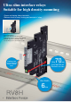


RV8H Interface Relays
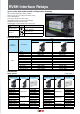
Marking Plate Package Quantity: 1
Shape Marking Part No.
No marking
Material: PBT (white)
Blank SV9Z-PW10
Vertical laser marking
123456789
10
Material: PBT (white)
1 2 3 4 5 6 7 8 9 10
SV9Z-PW10-V1-10
11 12 13 14 15 16 17 18 19 20
SV9Z-PW10-V11-20
21 22 23 24 25 26 27 28 29 30
SV9Z-PW10-V21-30
31 32 33 34 35 36 37 38 39 40
SV9Z-PW10-V31-40
41 42 43 44 45 46 47 48 49 50
SV9Z-PW10-V41-50
51 52 53 54 55 56 57 58 59 60
SV9Z-PW10-V51-60
61 62 63 64 65 66 67 68 69 70
SV9Z-PW10-V61-70
71 72 73 74 75 76 77 78 79 80
SV9Z-PW10-V71-80
81 82 83 84 85 86 87 88 89 90
SV9Z-PW10-V81-90
91 92 93 94 95 96 97 98 99
100
SV9Z-PW10-V91-100
A B C D E F G H I J
SV9Z-PW10-VA-J
K L M N O P Q R S T
SV9Z-PW10-VK-T
U V W X Y Z
SV9Z-PW10-VU-Z
SV9Z-PW10-VGROUND
SV9Z-PW10-VAC
Horizontal laser marking
1
2
3
4
5
6
7
8
9
10
Material: PBT (white)
1
2
3
4
5
6
7
8
9
10
SV9Z-PW10-H1-10
11
12
13
14
15
16
17
18
19
20
SV9Z-PW10-H11-20
21
22
23
24
25
26
27
28
29
30
SV9Z-PW10-H21-30
31
32
33
34
35
36
37
38
39
40
SV9Z-PW10-H31-40
41
42
43
44
45
46
47
48
49
50
SV9Z-PW10-H41-50
51
52
53
54
55
56
57
58
59
60
SV9Z-PW10-H51-60
61
62
63
64
65
66
67
68
69
70
SV9Z-PW10-H61-70
71
72
73
74
75
76
77
78
79
80
SV9Z-PW10-H71-80
81
82
83
84
85
86
87
88
89
90
SV9Z-PW10-H81-90
91
92
93
94
95
96
97
98
99
100
SV9Z-PW10-H91-100
A
B
C
D
E
F
G
H
I
J
SV9Z-PW10-HA-J
K
L
M
N
O
P
Q
R
S
T
SV9Z-PW10-HK-T
U
V
W
X
Y
Z
SV9Z-PW10-HU-Z
SV9Z-PW10-HGROUND
SV9Z-PW10-HAC
Shape Material Part No. Package Quantity Note
Jumper
Rated current: 6A (Note)
Brass (nickel-plated)
with polyamide sheath
Approx. 6g
SV9Z-J20*PN10
10
Specify a color code in place of *
in the Part No.
B: black
W: gray
S: blue
Can be cut to required length.
No. of points: 20
DIN Rail Spacer Polyamide (gray) SV9Z-SA2W 1
Used for adjusting spacing
between sockets and to prevent
the ends of jumpers from
exposing.
Note: Ensure that the total current to the jumper does not exceed the rated current.
Applicable Ferrules
Applicable Wire
(stranded)
Part No. Manufacturer
mm
2
AWG
0.5 20 AI0.5-8WH
Phoenix
Contact
0.75 18 AI0.75-8GY
1 18 AI1-8RD
0.5 22 TE0.5-8
Nichifu
0.75 20 TE0.75-8
1 18 TE1.0-8
Specifications
Part No. RV8H-L (Screw Terminal) RV8H-S (Spring Clamp Terminal)
Number of Poles 1-pole
Contact Configuration SPDT
Contact Material Silver alloy (gold-plated)
Degree of Protection Relay: IP67, Socket: IP20 (IEC 60529)
Contact Resistance (initial value) 100mΩ maximum
Operate Time 15ms maximum
Release Time 20ms maximum
Insulation Resistance 1,000MΩ minimum (500V DC megger)
Dielectric
Strength
Between contact and coil 4,000V AC, 1 minute
Between contacts of the same pole 1,000V AC, 1 minute
Vibration
Resistance
Operation extremes 10 to 55 Hz, amplitude 0.5mm (NO contact), 0.2mm (NC contact)
Damage Limits 10 to 55 Hz, amplitude 0.5mm (NO contact), 0.2mm (NC contact)
Shock
Resistance
Operation extremes 49 m/s
2
(NO contact), 29.4 m/s
2
(NC contact)
Damage Limits 980 m/s
2
Electrical Life (rated load)
30,000 operations minimum (NO contact), 10,000 operations minimum (NC contact)
(250V AC/30V DC, 6A resistive load, operation frequency 1,800 operations per hour)
Mechanical Life (no load) 10 million operations minimum (operation frequency 18,000 operations/hour)
Operating Temperature
RV8H-*-D6, D9, D12, D18, D24, AD12, AD18, AD24, AD48, AD60: –40 to +70°C (no
freezing) RV8H-*-AD110, AD220: –40 to +55°C (no freezing)
Operating Humidity 5 to 85% RH (no condensation)
Storage Temperature –40 to +85°C (no freezing)
Storage Humidity 5 to 85% RH (no condensation)
Weight (approx.) 30g 26g
Contact Ratings
Allowable Contact Power Rated Load
Allowable
Switching
Current
Allowable
Switching
Voltage
Minimum Applicable
Load
Resistive Load Inductive Load Voltage
Resistive
Load
Inductive
Load
1,500VA AC
180W DC
B300/R300
(pilot duty)
250V AC
30V DC
6A
6A
B300/R300
(pilot duty)
6A
400V AC
125V DC
6V DC, 10 mA
(reference value)
Coil Ratings
Rated Voltage (V)
Coil
Voltage
Code
Rated
Current (mA)
±15% (at 23°C)
(Note)
Coil
Resistance (Ω)
±15% (at 23°C)
(Note)
Impedance (Ω)
±15%
(at 23°C)
Operating Characteristics
(against rated values at 23°C)
Power
Consumption
Maximum
Continuous
Applied Voltage
(Note)
Minimum
Pickup
Voltage
Dropout
Voltage
DC
6V DC D6 35 170
110%
90%
maximum
7%
minimum
0.21
9V DC D9 18.6 485
0.212V DC D12 14.6 820
18V DC D18 11.6 1,550
24V DC D24 10.6 2,270 0.25
AC/
DC
12V AC/DC AD12 15.5 800 755 0.2
18V AC/DC AD18 13.3 1,345 1,365 0.25
24V AC/DC AD24 13.7 1,790 1,730 0.33
48V AC/DC AD48 4.0 12,230 11,880
0.2
60V AC/DC AD60 3.4 17,910 17,600
110-125V AC/DC
AD110 3.4-3.9 32,450-32,900
31,790-31,890
0.5
220-240V AC/DC
AD220 3.3-3.6 65,940-68,570
65,670-66,070
0.85
Note: D12 and below: ±10%
UL and c-UL Ratings
Voltage Resistive Inductive
250V AC 6A
B300/R300
(pilot duty)
30V DC 6A
VDE Ratings (RV1H relay only)
Voltage Resistive
250V AC 6A
30V DC 6A
5