RF1V Force Guided Relays SF1V Relay Sockets (090319)
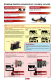
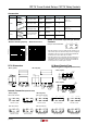
Enables flexible construction of safety circuits Complies with International Standards Compact and Slim Force guided contact mechanism (EN50205 Type A TÜV approved) Compact size enables size reduction of PC board. 4-pole type: 13W × 40D × 24H mm 6-pole type: 13W × 50D × 24H mm Fast Response Time Socket Variation Response time of 8 ms. Ensures safety by turning the load off quickly. (200 m/s2 minimum) PC board mount and DIN rail mount sockets are available.
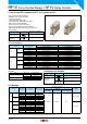
RF1V Force Guided Relays / SF1V Relay Sockets Compact and EN compliant RF1V force guided relays. • Force guided contact mechanism (EN50205 Type A TÜV approved) • Contact configuration 4-pole (2NO-2NC, 3NO-1NC) 6-pole (4NO-2NC, 5NO-1NC, 3NO-3NC) • Built-in LED indicator available. • Fast response time (8 ms maximum). • High shock resistance (200 m/s2 minimum) • Finger-safe DIN rail mount socket and PC board mount socket. Applicable Standard Certification Organization / File No. Marking UL508 CSA C22.
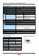
RF1V Force Guided Relays / SF1V Relay Sockets Number of Poles Contact Configuration Contact Resistance (initial value) (Note 1) Contact Material Rated Load (resistive load) Allowable Switching Power (resistive load) Allowable Switching Voltage Allowable Switching Current Minimum Applicable Load (Note 2) Power Consumption (approx.
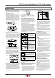
RF1V Force Guided Relays / SF1V Relay Sockets Accessories Item Appearance Specifications DIN Rail Type No. Package Quantity Aluminum Weight: Approx. 200g BAA1000 Steel Weight: Approx. 320g BAP1000 BAP1000PN10 10 Aluminum Weight: Approx. 250g BNDN1000 BNDN1000 1 BNL5 BNL5PN10 10 BNL6 BNL6PN10 10 Characteristics • Maximum Switching Capacity BAA1000PN10 Remarks 10 Length: 1m Width: 35 mm Metal (zinc plated steel) Weight: Approx. 15g End Clip Ordering Type No.
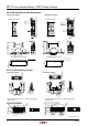
RF1V Force Guided Relays / SF1V Relay Sockets SF1V DIN Rail Mount Socket Dimensions • SF1V-6-07L (6-pole) (Internal Connection) M3 Terminal Screw 8 7 12 13 11 6 10 8 9 7 6 4 5 ø6.2 4 2 2 5 1 (Top View) R2 1 ø6.2 3 (Top View) 6.5 3 M3 Terminal Screw 75 75 14 9 6.5 6.5 (Internal Connection) 10 4 6.5 5 4 5 • SF1V-4-07L (4-pole) R2 6.3 5.3 5.3 62.4 58.9 62.4 58.9 6.3 22.4 35.4 29.8 4 4 35.4 (Panel Mounting Hole Layout) (Panel Mounting Hole Layout) 80.0 ±0.
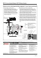
RF1V Force Guided Relays / SF1V Relay Sockets Instructions 1. Driving Circuit for Relays Smoothing Capacitor + – R Relay Pulsation DC Emin Emax Emean Ripple Factor (%) Emax – Emin × 100% Emean Emax = Maximum of pulsating current Emin = Minimum of pulsating current Emean = DC mean value 3. Operating the relay in sync with an AC load: If the relay operates in sync with AC power voltage of the load, the relay life may be reduced.
RF1V Force Guided Relays/ SF1V Relay Sockets Control circuits conforming with safety categories 2, 3, and 4 can be constructed. • Safety category 4 control circuits The circuit example below consisting of interlock switches, force guided relays, and safety contactors are only a part of a safety-related system in a machine.