
User manual

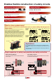
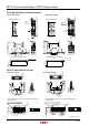
7
RF1V Force Guided Relays / SF1V Relay Sockets
Instructions
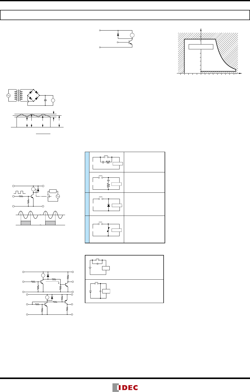
1. Driving Circuit for Relays
1. To make sure of correct relay operation, apply
rated voltage to the relay coil. Pickup and drop-
out voltages may differ according to operating
temperature and conditions.
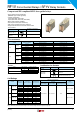
2. Input voltage for DC coil:
A complete DC voltage is best for the coil power
to make sure of stable operation. When using a
power supply containing a ripple voltage, sup-
press the ripple factor within 5%. When power
issuppliedthrougharecticationscircuit,relay
operating characteristics, such as pickup volt-
age and dropout voltage, depend on the ripple
factor. Connect a smoothing capacitor for better
operating characteristics as shown below.
+
–
R
Smoothing
Capacitor
Relay
Pulsation
Emin Emax Emean
DC
Ripple Factor (%) × 100%
Emax –
Emin
Emax= Maximum of pulsating current
Emin= Minimum of pulsating current
Emean = DC mean value
Emean
3. Operating the relay in sync with an AC load:
If the relay operates in sync with AC power volt-
age of the load, the relay life may be reduced. If
this is the case, select a relay in consideration of
the required reliability for the load. Or, make the
relay turn on and off irrespective of the AC power
phase or near the point where the AC phase
crosses zero voltage.
R
Vin
EAC
TE
Load
V
in
E
AC
4. Leakage current while relay is off:
When driving an element at the same time as
the relay operation, special consideration is
needed for the circuit design. As shown in the
incorrect circuit below, leakage current (Io)
owsthroughtherelaycoilwhiletherelayisoff.
Leakage current causes coil release failure or
adversely affects the vibration resistance and
shock resistance. Design a circuit as shown in
the correct example.
Incorrect
R
TE
lo
Correct
R
5. Surge suppression for transistor driving circuits:
When the relay coil is turned off, a high-voltage
pulse is generated. Be sure to connect a diode
to suppress the counter electromotive force.
Then, the coil release time becomes slightly
longer. To shorten the coil release time, connect
a Zener diode between the collector and emitter
of the controlling transistor. Select a Zener diode
with a Zener voltage slightly higher than the
power voltage.
R
Counter emf
suppressing diode
Relay
+
–
6. The coil terminal of the relay has polarity.
Connect terminals according to the internal
connection diagram. Incorrect wiring may cause
malfunction.
2. Protection for Relay Contacts
1. The contact ratings show maximum values.
Make sure that these values are not exceeded.
Whenaninrushcurrentowsthroughtheload,
the contact may become welded. If this is the
case, connect a contact protection circuit, such
as a current limiting resistor.
2. Contact protection circuit:
When switching an inductive load, arcing causes
carbides to form on the contacts, resulting in an
increased contact resistance. In consideration
of contact reliability, contact life, and noise
suppression, use of a surge absorbing circuit
is recommended. Note that the release time
of the load becomes slightly longer. Check the
operation using an actual load. Incorrect use of
a contact protection circuit will adversely affect
switching characteristics. Four typical examples
of contact protection circuits are shown in the
following table:
RC
Power
CR
Ind. Load
This protection circuit can be
used when the load impedance is
smaller than the RC impedance in
an AC load power circuit.
R: Resistor of approximately the
same resistance value as the load
C:0.1to1μF
C
R
Power
Ind. Load
This protection circuit can be used
for both AC and DC load power
circuits.
R: Resistor of approximately the
same resistance value as the load
C:0.1to1μF
Diode
+
–
D
Power
Ind. Load
This protection circuit can be used
for DC load power circuits. Use a
diode with the following ratings.
Reverse withstand voltage:
Power voltage of the load circuit
× 10
Forward current:
More than the load current
Varistor
Varistor
Power
Ind. Load
This protection circuit can be used
for both AC and DC load power
circuits.
For a best result, when using on a
power voltage of 24 to 48V AC/DC,
connect a varistor across the load.
When using on a power voltage
of 100 to 240V AC/DC, connect a
varistor across the contacts.
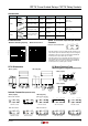
3. Do not use a contact protection circuit as shown
below:
Power
C
Load
This protection circuit is very effective in arc
suppression when opening the contacts. But,
the capacitor is charged while the contacts
are opened. When the contacts are closed,
the capacitor is discharged through the
contacts, increasing the possibility of contact
welding.
C
Load
Power
This protection circuit is very effective in arc
suppression when opening the contacts.
But, when the contacts are closed, a current
owstochargethecapacitor,causingcontact
welding.
Generally,switchingaDCinductiveloadismoredifcult
than switching a DC resistive load. Using an appropriate
arc suppressor will improve the switching characteristics of
a DC inductive load.
3. Usage, transport, and storage conditions
1. Temperature, humidity, atmospheric pressure
during usage, transport, and storage.
➀ Temperature: –45°C to +85°C (no freezing)
When the temperature is 70 to 80°C, reduce
the 6A max. switching current by 0.1 A/°C
➁ Humidity: 5 to 85%RH (no condensation)
The humidity range varies with temperature.
Use within the range indicated in the chart
below.
➂ Atmospheric pressure: 86 to 106 kPa
Operating temperature and humidity range
Tolerance Range
(Avoid freezing
when using at
temperatures
below 0ºC)
(Avoid
condensation
when using at
temperatures
above 0ºC)
85
5
0–40
85
Humidity (%RH)
Temperature (ºC)
2. Condensation
Condensation occurs when there is a sudden
change in temperature under high temperature
and high humidity conditions. The relay insula-
tion may deteriorate due to condensation.
3. Freezing
Condensation or other moisture may freeze on
the relay when the temperatures is lower than
0ºC. This causes problems such as sticking of
movable parts or delay in operation.
4. Low temperature, low humidity environments
Plastic parts may become brittle when used in
low temperature and low humidity environments.
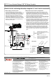
4. Panel Mounting
When mounting DIN rail mount sockets on a panel,
take the following into consideration.
Use M3.5 screws, spring washers, and hex nuts.•
For mounting hole layout, see page 6.•
Keep the tightening torque within 0.49 to 0.68 •
N
·
m. Excessive tightening may cause damage to
the socket.
5. Others
1. General notice:
➀ To maintain the initial characteristics, do not
drop or shock the relay.
➁ The relay cover cannot be removed from the
base during normal operation. To maintain
the initial characteristics, do not remove the
relay cover.
➂ Use the relay in environments free from
condensation, dust, sulfur dioxide (SO
2
), and
hydrogensulde(H
2
S).
➃ The RF1V relay cannot be washed as it is not
asealedtype.Alsomakesurethatuxdoes
not leak to the PC board and enter the relay.
2. Connecting outputs to electronic circuits:
When the output is connected to a load which
responds very quickly, such as an electronic
circuit, contact bouncing causes incorrect opera-
tion of the load. Take the following measures
into consideration.
➀ Connect an integration circuit.
➁ Suppress the pulse voltage due to bouncing
within the noise margin of the load.
3. Do not use relays in the vicinity of strong mag-
neticeld,asthismayaffectrelayoperation.
4. UL and CSA ratings may differ from product
rated values determined by IDEC.
6. Notes on PC Board Mounting
When mounting 2 or more relays on a PC board, •
keep a minimum spacing of 10 mm in each
direction. If used without spacing of 10 mm,
rated current and operating temperature differs.
Consult IDEC.
Manual soldering: Solder the terminals at 400°C•
within 3 sec.
Auto-soldering: Preliminary heating at 120°C •
within 120 sec. Solder at
260°C±5°C within 6 sec.
Becausetheterminalpartislledwithepoxy•
resin, do not excessively solder or bend the
terminal. Otherwise, air tightness will degrade.
Avoid the soldering iron from touching the relay •
coverortheepoxylledterminalpart.
Useanon-corrosiveresinux.
(090319)