
User guide

2: MODULE SPECIFICATIONS
2-50 « FC4A MICROSMART USER’S MANUAL »
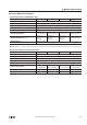
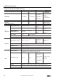
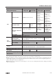
Analog Input Specifications (Ladder Refresh Type)
Note 1: Total input system transfer time = Sample repetition time + Internal processing time
The total input system transfer time increases in proportion to the number of channels used.
Note 2: The data processed in the analog I/O module can be linear-converted to a value between –32768 and 32767. The
optional range designation, and analog I/O data minimum and maximum values can be selected using data registers allo-
cated to analog I/O modules. See page 24-12.
Note 3: When an error is detected, a corresponding error code is stored to a data register allocated to analog I/O operating
status. See page 24-6.
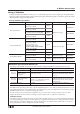
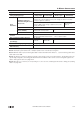
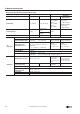
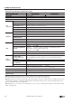
Type No. FC4A-J8AT1
Analog Input Signal Type NTC Thermistor PTC Thermistor
Input Range –50 to 150°C
Applicable Thermistor 100 kΩ maximum
Input Detection Current 0.1 mA
AD
Conversion
Sample Duration Time 2 ms maximum
Sample Repetition Time 2 ms maximum
Total Input System
Transfer Time (Note 1)
10 ms × channels + 1 scan time (Note 1)
Type of Input Single-ended input
Operating Mode Self-scan
Conversion Method Successive approximation register method
Input Error
Maximum Error at 25°C ±0.2% of full scale
Temperature Coefficient ±0.005% of full scale/°C
Repeatability after
Stabilization Time
±0.5% of full scale
Non-lineality No
Maximum Error ±1% of full scale
Data
Digital Resolution Approx. 4000 increments (12 bits)
Input Value of LSB 0.05°C
Data Type in Application
Program
Default: 0 to 4000
Optional: –32768 to 32767 (selectable for each channel) (Note 2)
Temperature: Celsius, Fahrenheit (NTC only)
Resistance: 0 to 10000
Monotonicity Yes
Input Data Out of Range Detectable (Note 3)
Noise
Resistance
Maximum Temporary
Deviation during
Electrical Noise Tests
±3% maximum
(when a 500V clamp voltage is applied to the power supply and I/O lines)
Input Filter Software
Recommended Cable for
Noise Immunity
—
Crosstalk 2 LSB maximum
Isolation
Between input and power circuit: Isolated
Between input and internal circuit: Photocoupler-isolated
Effect of Improper Input Connection No damage
Selection of Analog Input Signal Type Using programming software
Calibration or Verification to Maintain
Rated Accuracy
Not possible