
User guide

2: MODULE SPECIFICATIONS
« FC4A MICROSMART USER’S MANUAL » 2-47
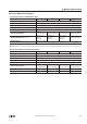
Note 1: Values in ( ) represent analog I/O modules earlier than version 200. For analog I/O module version, see page 2-44.
Note 2: Total input system transfer time = Sample repetition time + Internal processing time
Note 3: Minimum values represent analog input data in Celsius and Fahrenheit. Values in ( ) represent analog I/O modules
earlier than version 200.
Note 4: The data processed in the analog I/O module can be linear-converted to a value between –32768 and 32767. The
optional range designation, and analog I/O data minimum and maximum values can be selected using data registers allo-
cated to analog I/O modules. See page 24-12.
Note 5: When an error is detected, a corresponding error code is stored to a data register allocated to analog I/O operating
status. See page 24-6.
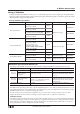
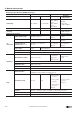
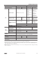
Noise
Resistance
Maximum Temporary
Deviation during Electrical
Noise Tests
±1% maximum
(when 1 kV is directly applied to the power supply line and a 1 kV clamp
voltage is applied to I/O lines)
(±3% maximum) (Note 1)
(when a 500V clamp voltage is applied to the power
supply and I/O lines)
(Not assured)
(Note 1)
Input Filter No
Recommended Cable for
Noise Immunity
Twisted pair shielded cable —
Crosstalk 2 LSB maximum
Isolation
Between input and power circuit: Isolated
Between input and internal circuit: Photocoupler-isolated
Effect of Improper Input Connection No damage
Maximum Permanent Allowed Overload
(No Damage)
13V DC 40 mA DC —
Selection of Analog Input Signal Type Using programming software
Calibration or Verification to Maintain
Rated Accuracy
Not possible
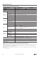
Type No. FC4A-L03A1 / FC4A-J2A1 FC4A-L03AP1
Analog Input Signal Type Voltage Input Current Input Thermocouple
Resistance
Thermometer