
User guide

2: MODULE SPECIFICATIONS
2-44 « FC4A MICROSMART USER’S MANUAL »
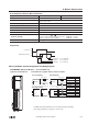
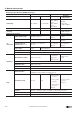
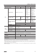
Parts Description
(1) Expansion Connector Connects to the CPU and other I/O modules.
(The all-in-one 10- and 16-I/O type CPU modules cannot be connected.)
(2) Module Label Indicates the analog I/O module Type No. and specifications.
Four analog I/O modules FC4A-L03A1, FC4A-L03AP1, FC4A-J2A1, and FC4A-K1A1 of
version 200 or higher have the version number indicated on the module label
attached to the side of the module. Confirm the version number because some
specifications differ depending on the version number. Analog I/O modules earlier
than version 200 do not have a version number indicated on the module label.
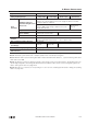
(3) Power LED (PWR) END refresh type FC4A-L03A1, FC4A-L03AP1, FC4A-J2A1, FC4A-K1A1:
Turns on when power is supplied to the analog I/O module.
(3) Status LED (STAT) Ladder refresh type FC4A-J4CN1, FC4A-J8C1, FC4A-J8AT1, FC4A-K2C1:
Indicates the operating status of the analog I/O module.
(4) Terminal No. Indicates terminal numbers.
(5) Cable Terminal All analog I/O modules have a removable terminal block.
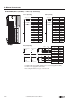
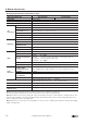
Status LED Analog Input Operating Status
OFF Analog I/O module is stopped
ON Normal operation
Flash
Initializing
Changing configuration
Hardware initialization error
External power supply error
The terminal style depends on the model of analog I/O modules.
(1) Expansion Connector
(2) Module Label
(3) Power LED (PWR)
(4) Terminal No.
(5) Cable Terminal
(3) Status LED (STAT)
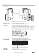
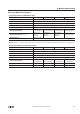
Analog I/O Module Version